
Surface-mounted piezoelectric micropump and manufacturing method thereof

A manufacturing method and a surface-mounted technology, applied in the direction of variable capacity pump parts, pumps, pump components, etc., can solve the problems of piezoelectric micro-pump failure, low integration, large volume, etc., and achieve small size and convenient use , high chemical stability

Active Publication Date: 2020-04-10
CHINA ELECTRONICS TECH GRP NO 26 RES INST
View PDF10 Cites 1 Cited by
  • Summary
  • Abstract
  • Description
  • Claims
  • Application Information

AI Technical Summary

Problems solved by technology

[0003] However, there are some technical problems in piezoelectric micropumps at present: one is the interface problem. The fluid interface of piezoelectric micropumps generally realizes fluid in and out transfer through tubular structures, and most of the electrical interfaces that supply power to piezoelectric micropumps use "flying The piezoelectric micropump interface has the disadvantages of large volume and low integration; the second is that the piezoelectric vibrator as the driving component is placed on the outer surface of the piezoelectric micropump, and when there is a large pressure difference between the inside and outside of the fluid circuit, Piezoelectric micropumps will fail due to the inability of the piezoelectric vibrator to vibrate

Method used


Image

  • Surface-mounted piezoelectric micropump and manufacturing method thereof
  • Surface-mounted piezoelectric micropump and manufacturing method thereof
  • Surface-mounted piezoelectric micropump and manufacturing method thereof

Examples


Embodiment Construction

[0039] The specific implementation manners of the present invention will be further described in detail below in conjunction with the embodiments in the accompanying drawings.

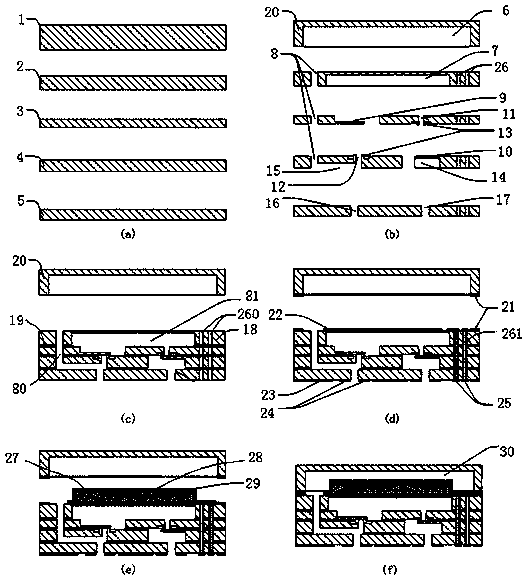
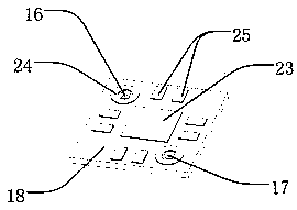
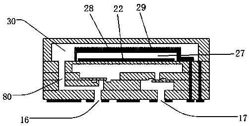
[0040] Surface-mounted piezoelectric micropump of the present invention, its structure can refer to image 3 and Figure 4 , including a pump body, a liquid inlet valve plate, a liquid discharge valve plate, and a piezoelectric vibrator. The pump body is provided with a central sinking cavity, an inflow sinking cavity, and an outflow sinking cavity. The inflow sinking cavity and the outflow sinking cavity are located at the same height. The center sinking cavity is located above the inflow sinking cavity and the outflow sinking cavity, the inflow sinking cavity and the center sinking cavity are connected through the liquid inlet hole, and the center sinking cavity and the outflow sinking cavity are connected through the drain hole; the liquid inlet valve plate is installed in the center The bottom of ...


PUM


Abstract

The invention discloses a surface-mounted piezoelectric micropump and a manufacturing method thereof. The manufacturing method comprises the following steps that firstly, five substrates are prepared,and the substrate one to the substrate five are sequentially arranged from top to bottom; ducts and cavities of the five substrates are designed and machined according to the structural characteristics of the micropump; the first substrate forms a top cover, and the second substrate to the fifth substrate are stacked and bonded together to form a pump body; a metal seed layer is deposited on theinner wall of a metal through hole of the pump body, and the corresponding metal is deposited through an electroplating process to fill the metal through hole to form a conductive channel; required patterned metal layers are manufactured on the bottom surface of the top cover and the top surface and the bottom surface of the pump body correspondingly; a piezoelectric vibrator, a top electrode andan insulating layer are sequentially formed on the top surface of the pump body; and finally, the top cover and the pump body are welded together. The method is simple in machining, easy to realize, high in machining precision and capable of being produced in batches at low cost, and the prepared piezoelectric micropump has the characteristics of small volume, light weight, integrated packaging interfaces and large output flow, and is suitable for closed fluid circuits.

Description

technical field [0001] The invention relates to a piezoelectric micropump, and at the same time relates to a manufacturing method of a piezoelectric micropump, belonging to the technical fields of microelectromechanical systems, fluid drive, microsystem liquid cooling and heat dissipation, and biomedicine. Background technique [0002] In recent years, with the rapid development of microelectromechanical systems (MEMS) technology, piezoelectric micropumps have attracted widespread attention in thermal management, biomedical and other technical fields due to their unique advantages such as small size, low power consumption, and high output pressure. For example, in 2016, Luo Wenbo and others from the University of Electronic Science and Technology of China proposed a patent in the published invention patent (Chinese patent publication number is CN105977370, and the title of the invention is "an embedded refrigeration device based on a piezoelectric micropump and its preparatio...

Claims


Application Information

Patent Timeline
Patent Type & Authority Applications(China)
IPC IPC(8): F04B43/04F04B53/10F04B53/16B23P15/00C23C14/04C23C14/16C23C14/24C23C14/34C23C16/00C23C18/31C25D3/38C25D3/48
CPCF04B43/046F04B53/16F04B53/102B23P15/00C23C14/165C23C18/31C25D3/38C25D3/48C23C14/04C23C14/16C23C14/24C23C14/34C23C16/00
Inventor 余怀强
Owner CHINA ELECTRONICS TECH GRP NO 26 RES INST
Learn More