
Antenna module for simulating terminal radiation and in-vehicle electromagnetic radiation test system and method

An antenna module and analog terminal technology, applied in the fields of electromagnetic field characteristics, radiating element structure, antenna grounding switch structure connection, etc., can solve the problems of poor test data consistency, achieve standardization and repeatability, convenient and fast adjustment, The effect of simple structure

Pending Publication Date: 2020-04-10
CHINA AUTOMOTIVE ENG RES INST +1
View PDF17 Cites 2 Cited by
  • Summary
  • Abstract
  • Description
  • Claims
  • Application Information

AI Technical Summary

Problems solved by technology

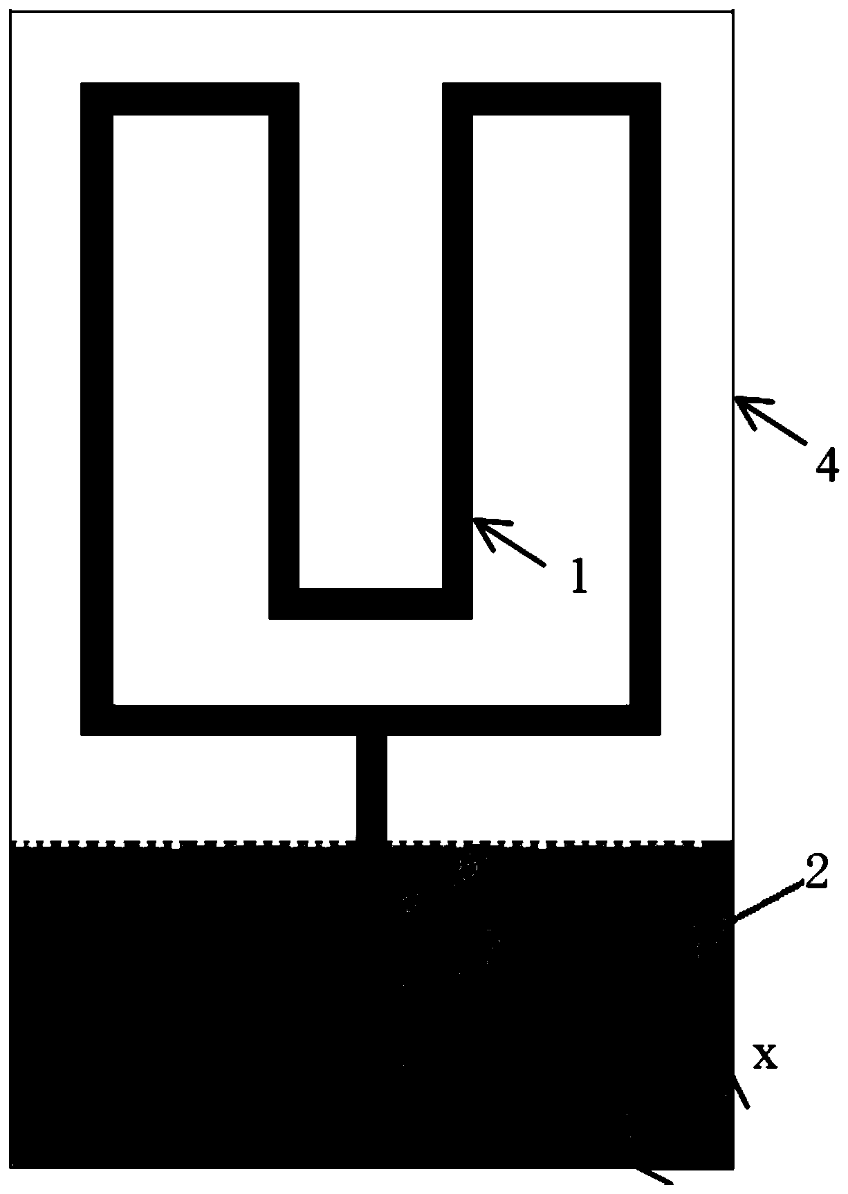
[0005] The beneficial effects of the above technical solution are: the antenna module uses a microstrip structure as the antenna body to radiate radio frequency signals, and the ground layer only covers all or part of the feeder line on the second surface, so that the antenna module has good omnidirectionality and little radiation. The radiation power of the belt can be adjusted to highly simulate the electromagnetic radiation of different manufacturers' terminal equipment (such as mobile phones) in various working modes (such as calling, uploading data or downloading data, etc.), which solves the problem of direct use of terminal equipment for radiation testing. The problem of poor test data consistency caused by different terminal equipment manufacturers, placement postures and test placement locations; and the antenna module also has the beneficial effects of simple structure and easy processing

Method used


Image

  • Antenna module for simulating terminal radiation and in-vehicle electromagnetic radiation test system and method
  • Antenna module for simulating terminal radiation and in-vehicle electromagnetic radiation test system and method
  • Antenna module for simulating terminal radiation and in-vehicle electromagnetic radiation test system and method

Examples


Embodiment Construction

[0031] Embodiments of the present invention are described in detail below, examples of which are shown in the drawings, wherein the same or similar reference numerals designate the same or similar elements or elements having the same or similar functions throughout. The embodiments described below by referring to the figures are exemplary only for explaining the present invention and should not be construed as limiting the present invention.

[0032] In the description of the present invention, unless otherwise specified and limited, it should be noted that the terms "installation", "connection" and "connection" should be understood in a broad sense, for example, it can be mechanical connection or electrical connection, or two The internal communication of each element may be directly connected or indirectly connected through an intermediary. Those skilled in the art can understand the specific meanings of the above terms according to specific situations.

[0033] The present ...


PUM


Abstract

The invention provides an antenna module for simulating terminal radiation and an in-vehicle electromagnetic radiation test system and method. The antenna module comprises a substrate; and the first surface of the substrate is provided with a radiation microstrip, a feeder line which is connected with the radiation microstrip and inputs a radio frequency signal to the radiation microstrip, and a power adjusting unit which is connected in series with the feeder line. A grounding layer is arranged on the second surface of the substrate, the first surface and the second surface are opposite, andthe grounding layer covers all or part of the feeder lines on the second surface. The antenna module has good omnidirectivity. The radiation power of the radiation micro-strip can be flexibly adjustedthrough the power adjusting unit; the electromagnetic radiation condition of the terminal equipment in various working modes can be highly simulated, and the problem of poor consistency of test datacaused by different manufacturers, placement postures and test placement positions of the terminal equipment when the terminal equipment is directly used for radiation test is solved. The system performs a radiation test in the microwave darkroom, can avoid external signal interference, and guides a user to reasonably place a terminal.

Description

technical field [0001] The invention relates to the field of electromagnetic radiation testing, in particular to an antenna module for simulating terminal radiation, an in-vehicle electromagnetic radiation testing system and a method. Background technique [0002] At present, automobiles are ushering in the major changes of intelligence, networking, and electrification, and the proportion of electronic components in the whole vehicle is increasing. However, while electronic equipment increases the intelligence and convenience of automobiles, it also brings A series of electromagnetic compatibility and human body electromagnetic radiation problems, the use of mobile terminal equipment carried by drivers and passengers, such as mobile phone calls, will aggravate the problem of human body electromagnetic radiation in the car. The existing human body electromagnetic protection testing technology is mainly for the 10Hz to 400KHz frequency band in the car, and there are fewer test...

Claims


Application Information

Patent Timeline
Patent Type & Authority Applications(China)
IPC IPC(8): H01Q1/36H01Q1/38H01Q1/50G01R29/08
CPCH01Q1/36H01Q1/38H01Q1/50G01R29/0878G01R29/0871
Inventor 耿东东高阳春陈睿黎小娇曾霞鲁毅
Owner CHINA AUTOMOTIVE ENG RES INST
Learn More