
Pre-charging circuit, inverter and power generation system

A pre-charging circuit and inverter technology, applied in battery circuit devices, flexible AC transmission systems, photovoltaic power generation, etc., can solve the problems of complex structure and high cost of pre-charging circuits

Active Publication Date: 2020-04-10
HUAWEI DIGITAL POWER TECH CO LTD
View PDF10 Cites 4 Cited by
  • Summary
  • Abstract
  • Description
  • Claims
  • Application Information

AI Technical Summary

Problems solved by technology

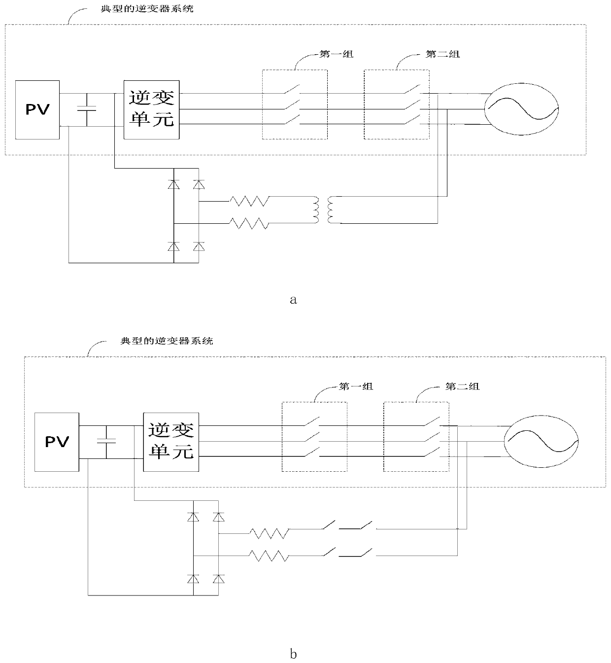
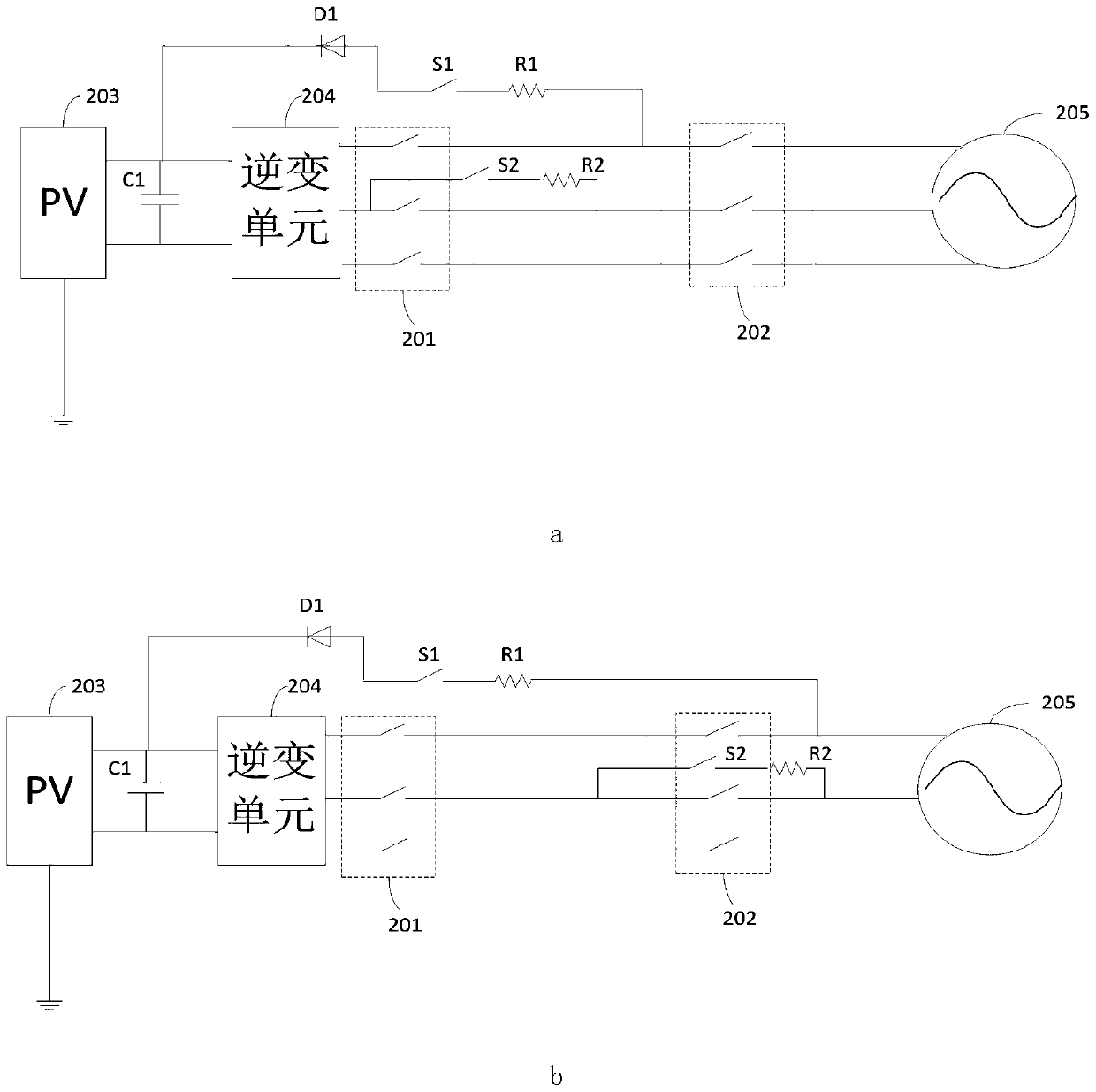
[0003] When the photovoltaic inverter is running in SVG mode, it is necessary to pre-charge the bus capacitor to avoid current impact due to the large voltage difference between the DC bus voltage and the peak voltage of the grid at the moment of grid connection. The current pre-charging circuit has a complex structure ,higher cost

Method used


Image

  • Pre-charging circuit, inverter and power generation system
  • Pre-charging circuit, inverter and power generation system
  • Pre-charging circuit, inverter and power generation system

Examples


Embodiment Construction

[0033] The embodiment of the present application provides a pre-charging circuit to avoid current impact caused by a large voltage difference between the DC bus voltage and the peak voltage of the grid at the moment of grid connection. The embodiment of the present application also provides a corresponding inverter and a power generation system.

[0034] Each will be described in detail below.

[0035] The following will clearly and completely describe the technical solutions in the embodiments of the application with reference to the drawings in the embodiments of the application. Apparently, the described embodiments are only some of the embodiments of the application, not all of them. Based on the embodiments in this application, all other embodiments obtained by those skilled in the art without making creative efforts belong to the scope of protection of this application.

[0036]The traditional power system needs to consume a large amount of non-renewable resources such ...


PUM


Abstract

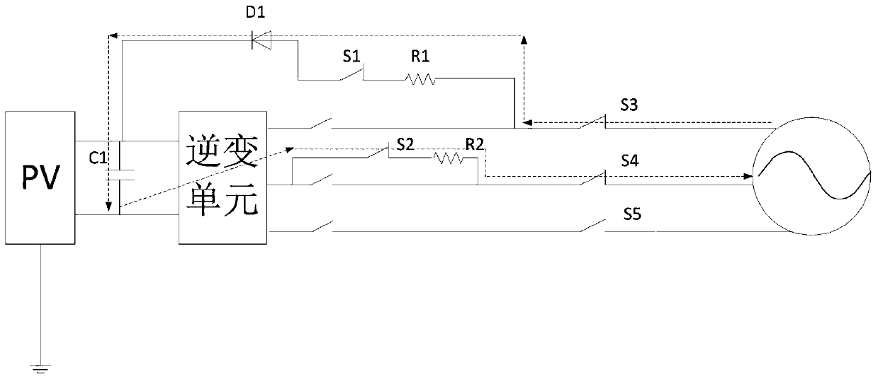
The invention discloses a pre-charging circuit which comprises a first switch, a second switch, a diode, a first current limiting device, a capacitor and an inversion unit. One end of the pre-chargingcircuit is connected with a power grid, after the first current limiting device, the first switch and the diode are connected in series, one end of the series connected structure is connected with one end of the capacitor, and the other end is connected with a first-phase alternating current of the power grid. The other end of the capacitor is connected to a second-phase alternating current of the power grid sequentially through the inversion unit and the second switch, after the first switch and the second switch are closed, the current outputted by the power grid passes through a closed loop formed by the first current limiting device, the first switch, the diode, the capacitor, the inversion unit and the second switch to charge the capacitor. The circuit for pre-charging the bus capacitor is provided, is simple in, is changed rarely on the basis of an existing inverter system, and saves the cost.

Description

technical field [0001] The present application relates to the technical field of photovoltaic power generation, in particular to a pre-charging circuit. Background technique [0002] The photovoltaic inverter is an energy conversion device in the photovoltaic power generation system, which is used to convert the direct current output by the photovoltaic cell into alternating current and then send it to the grid. The photovoltaic inverter is idle at night, but there is a need for reactive power compensation in the grid at night. In order to make full use of the photovoltaic inverter, the photovoltaic inverter can be used to supplement reactive power for the grid in real time at night, and realize the function of static var generator (static car generator, SVG) at night. [0003] When the photovoltaic inverter is running in SVG mode, it is necessary to pre-charge the bus capacitor to avoid current impact due to the large voltage difference between the DC bus voltage and the p...

Claims


Application Information

Patent Timeline
IPC IPC(8): H02M1/36H02J3/38
CPCH02M1/36H02M7/48H02M1/32H02J2300/22H02M7/125H02J3/381H02J2207/50Y02E10/56H02J2207/20H02J2300/24H02J7/35H02M7/44
Inventor 张彦忠叶海军姚晓锋
Owner HUAWEI DIGITAL POWER TECH CO LTD
Learn More