Multi-turn LTD pulse generator
A pulse generator and pulse voltage technology, which can be applied to electric pulse generator circuits, active components to generate pulses, and electromagnetic-magnetic devices to generate pulses. The effect of large adjustment range and small volume
- Summary
- Abstract
- Description
- Claims
- Application Information
AI Technical Summary
Problems solved by technology
Method used
Image
Examples
Embodiment 1
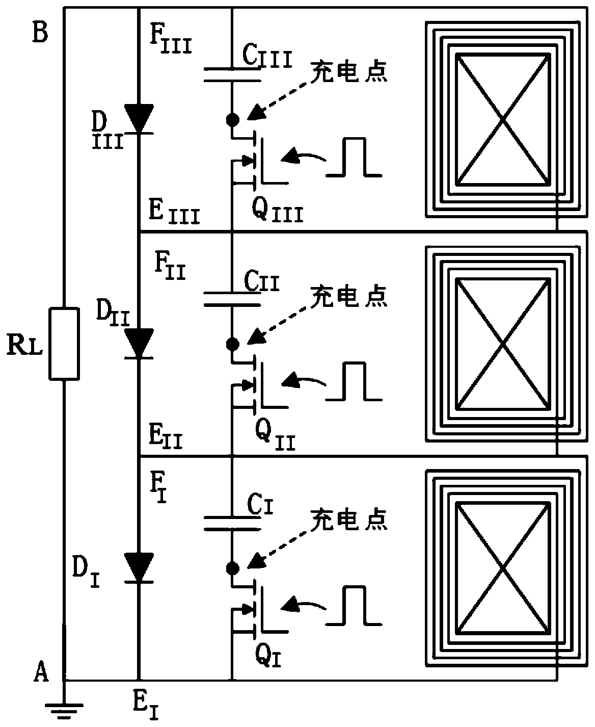
[0073] see figure 1 , three-stage all-solid-state multi-turn LTD pulse generator, mainly including resistor R L , Diode D I , Diode D II , Diode D III , switch tube Q I , switch tube Q II , switch tube Q III , Class I LTD module, Class II LTD module and Class III LTD module.
[0074] Preferably, the three-stage all-solid-state multi-turn LTD pulse generator can include a resistor R L , Diode D I , Diode D II , Diode D III , switch tube Q I , switch tube Q II , switch tube Q III , Several parallel I-level LTD modules, several parallel II-level LTD modules, and several parallel III-level LTD modules.
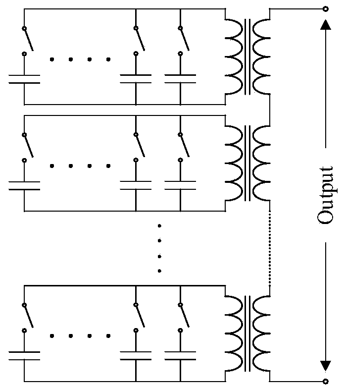
[0075] The equivalent circuit diagram of a three-stage all-solid-state multi-turn LTD pulse generator is shown in figure 2 shown. Diode D I , Diode D II , Diode D III It is a freewheeling device during discharge. The switch tube may be an IGBT, a thyristor, a GTO, and the like.
[0076] The circuit structure is as follows:
[0077] Note resistance R L The gr...
Embodiment 2
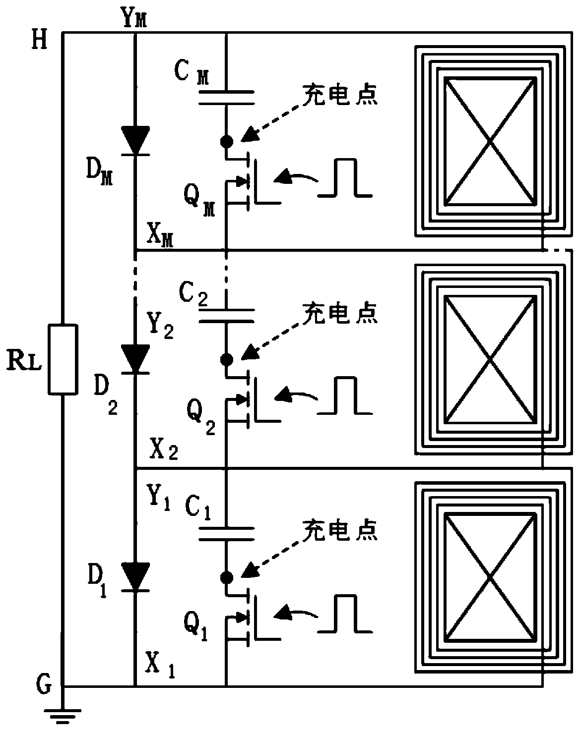
[0109] see image 3 and Figure 5 , M-class all-solid-state multi-turn LTD pulse generator, mainly including resistor R L , M diodes D i , M switching tubes Q i and M LTD modules. i=1,2,3...,M.
[0110] The circuit structure is as follows:
[0111] Note resistance R L The ground terminal of G is G, and the other end is H. Resistance R L The G terminal of the terminal is grounded, and the H terminal is connected in series with the diode D M the anode. Resistance R L The H end of the terminal is connected to the Y of the M-level LTD module M end. Resistance R L The G terminal is connected to the diode D 1 the negative pole. Resistance R L The G terminal is connected to the X of the Level 1 LTD module 1 end
[0112] Diode D i+1 The cathode of the series diode D i the anode. Diode D i+1 The cathode of X connected to the LTD module of level i+1 i+1 end. Diode D i+1 The cathode of the i-level LTD module is connected to the Y i end. X of the LTD module at l...
Embodiment 3
[0130] In the three-level all-solid-state multi-turn LTD pulse generator, the circuit structure of the i-level LTD module can be found in Figure 4 ,which is:
[0131] Note that the starting end of the N-turn coil wound on the core i is X i , ending in Y i .
[0132] Capacitance C i One end of the access Y i end, and the other end is connected in series with the switching tube Q i the drain. Switch tube Q i The gate is left floating. Switch tube Q i The source is connected to X i end.
[0133] When the switch tube Q i When turned on, the capacitor C i discharge. The current flows sequentially through the switch tube Q i , core i, capacitor C i , forming a loop L1, the current flows through the resistor R in turn L , The i-level LTD module then flows back to the resistor R L , forming the loop L2. Figure 4 The middle circuit L1 is regarded as the primary circuit of LTD, and the circuit L2 is regarded as the secondary circuit of LTD. It can be seen that the pr...
PUM
 Abstract
Description
Claims
Application Information
 - R&D
- Intellectual Property
- Life Sciences
- Materials
- Tech Scout
- Unparalleled Data Quality
- Higher Quality Content
- 60% Fewer Hallucinations
Browse by: Latest US Patents, China's latest patents, Technical Efficacy Thesaurus, Application Domain, Technology Topic, Popular Technical Reports.
© 2025 PatSnap. All rights reserved.Legal|Privacy policy|Modern Slavery Act Transparency Statement|Sitemap|About US| Contact US: help@patsnap.com


