
Frequency offset error control system based on linear frequency modulation signals

A linear frequency modulation signal and error control technology, which is applied in the field of ranging, can solve the problems that the ranging accuracy cannot meet the requirements of use, the cycle time of the sawtooth wave signal is short, and the frequency information is inaccurate, so as to reduce the sampling step size and reduce the phase noise. , the effect of speeding up the sweep speed

Inactive Publication Date: 2020-04-10
SHAANXI CHANGLING ELECTRONICS TECH
View PDF4 Cites 2 Cited by
  • Summary
  • Abstract
  • Description
  • Claims
  • Application Information

AI Technical Summary

Problems solved by technology

When at a short distance, because the cycle time of the sawtooth wave signal is short, the number of digital sampling points is small. When the fast Fourier transform (FFT) is used for spectrum analysis, the extracted frequency information is inaccurate due to the large frequency step and the small number of points, resulting in The short-distance ranging accuracy cannot meet the requirements of use

Method used


Image

  • Frequency offset error control system based on linear frequency modulation signals
  • Frequency offset error control system based on linear frequency modulation signals
  • Frequency offset error control system based on linear frequency modulation signals

Examples


Embodiment Construction

[0027] The implementation of the present invention will be described in detail below in conjunction with the accompanying drawings.

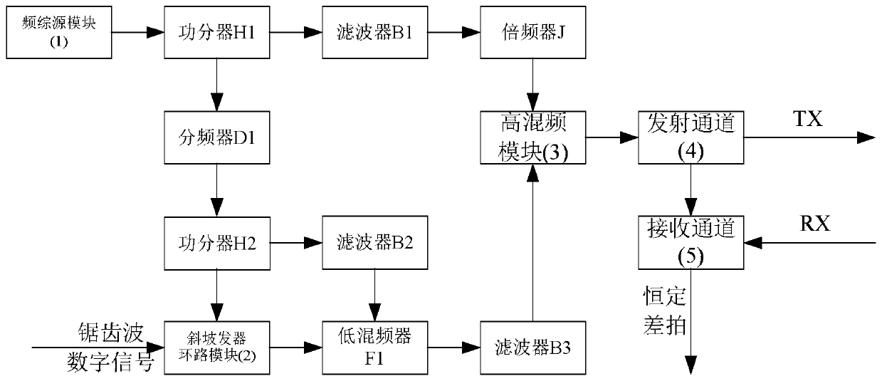
[0028] refer to figure 2 , the example of the present invention includes frequency synthesis source module 1, harmonic generator loop module 2, high frequency mixing module 3, transmitting channel 4, receiving channel 5, frequency multiplier J, low frequency mixer F1, frequency divider D1, Two power splitters H1, H2 and three filters B1, B2, B3. The output of the frequency synthesis source module 1 is connected to the input terminal of the first power divider H1, and the output of the first output terminal of the first power divider H1 passes through the first filter B1, the frequency multiplier J and the high frequency mixing module 3 in sequence. The input terminal is connected, the second output terminal of the first power divider H1 is connected with the input terminal of the second power divider H2 through the first frequency divider D1; ...


PUM


Abstract

The invention discloses a frequency offset error control system based on a linear frequency modulation signal, and mainly solves the problem that the modulation frequency offset error of a linear frequency modulation continuous wave signal is increased due to the fact that the modulation frequency offset of the existing linear frequency modulation signal changes along with the fluctuation of ambient temperature and modulation voltage. The system comprises a comprehensive source module and a ramp generator loop module, a high frequency mixing module and a transmitting channel, the comprehensivesource module outputs a dot frequency signal with high frequency stability; the signal is divided into two paths to be output through a power divider; wherein one path is subjected to frequency division and then mixed with a low-frequency linear frequency modulation signal output by the ramp generator loop module to generate a high-frequency linear frequency modulation signal, the high-frequencylinear frequency modulation signal is input into the high frequency mixing module, and the other path is subjected to frequency mixing with the high-frequency linear frequency modulation signal in thehigh frequency mixing module to generate a higher-frequency linear frequency modulation signal which is transmitted to an antenna transmitting port through a transmitting channel. The method can reduce the modulation frequency offset error of the linear frequency modulation signal, improves the frequency stability of the transmitted signal, and can be used for the distance measurement of a radarlinear frequency modulation continuous wave system.

Description

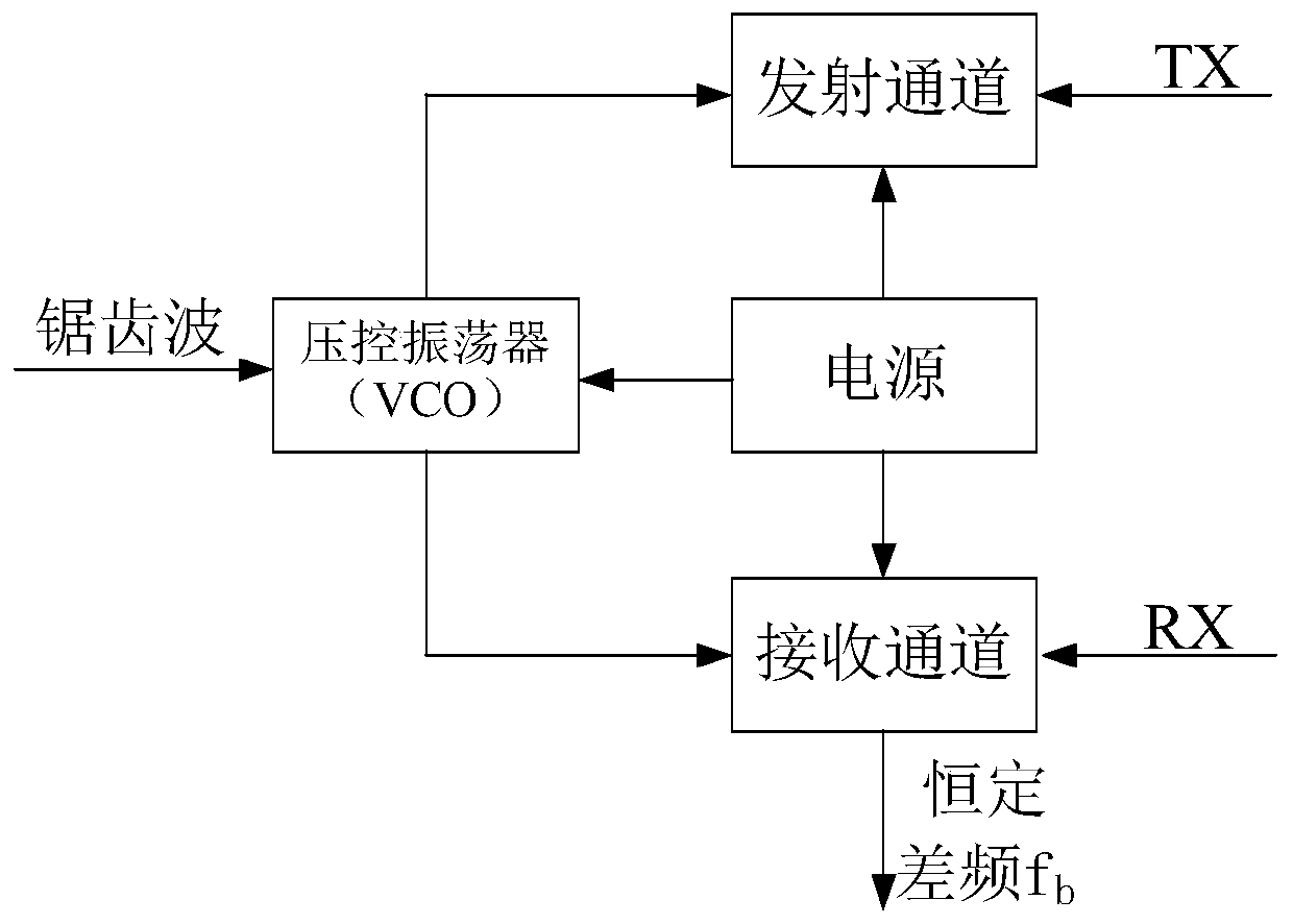
technical field [0001] The invention belongs to the technical field of distance measurement, and in particular relates to a linear frequency modulation signal frequency deviation error control system, which can be used for distance measurement of a radar linear frequency modulation continuous wave system, and improves the distance measurement accuracy of the radar. Background technique [0002] Linear frequency modulation continuous wave radar, its modulation waveform is a sawtooth wave, the period of the sawtooth wave signal is T, and the frequency modulation bandwidth is B. The sawtooth wave signal regulates the voltage-controlled oscillator of the radar to generate a linear frequency modulation continuous wave and transmits it. The transmitted signal is generated by target reflection. The echo signal after a certain time delay is received by the radar, and the radar mixes the echo signal with the replica of the transmitted signal, and then performs filtering, coherent dete...

Claims


Application Information

Patent Timeline
Patent Type & Authority Applications(China)
IPC IPC(8): H03L7/18G01S7/40G01S13/08
CPCH03L7/18G01S13/08G01S7/4004
Inventor 陈华解宝同陈坤冯伟
Owner SHAANXI CHANGLING ELECTRONICS TECH
Learn More