
Blow-moulded container used with oil film formed on inner surface

A blow molding, inner surface technology, applied in the field of blow molding containers, can solve problems such as uneven formation of liquid film

Inactive Publication Date: 2020-04-10
TOYO SEIKAN KAISHA LTD
View PDF2 Cites 0 Cited by
  • Summary
  • Abstract
  • Description
  • Claims
  • Application Information

AI Technical Summary

Problems solved by technology

[0008] However, when the liquid film is formed as described above to improve the slipperiness against viscous substances, the liquid film on the surface may sometimes be formed unevenly, causing the inconvenience that viscous substances will adhere to a part of the surface of the substrate

Method used


Image

  • Blow-moulded container used with oil film formed on inner surface
  • Blow-moulded container used with oil film formed on inner surface

Examples


Embodiment

[0085] The effects of the present invention will be described below with reference to experimental examples.

[0086] Methods for measuring various characteristics, physical properties, etc., and resins used for molding blow-molded containers, etc., in Experimental Examples are described below.

[0087] 1. Measurement of the surface roughness of the inner surface of the bottle

[0088] A 10 mm×10 mm test piece was cut out from the body portion of the bottle formed by the method described later for 3D shape measurement of the inner surface of the bottle body portion by using a microscope (VK-100 manufactured by KEYENCE CORPORATION). From the data thus obtained, the surface roughness of a 500 μm×500 μm area was calculated (ISO25178-2:2012).

[0089] 2. Measurement of the 2D line roughness of the inner surface of the bottle

[0090] A test piece of 20 mm x 20 mm was cut out from the main body of the bottle formed by the method described later to measure the surface roughness by...

experiment example 1

[0116] Low-density polyethylene (LDPE-A) as a resin for forming an outer layer was supplied to the 40 mm extruder-A. A blend material (resin for barrier layer formation) of ethylene-vinyl alcohol copolymer (EVOH) and polyolefin was supplied to 40 mm extruder-B. The 50mm extruder is supplied with low-density polyethylene (LDPE-A) as the resin for forming the middle layer, and the 40mm extruder-C is supplied with low-density polyethylene (LDPE-A) as the resin for forming the inner layer. B). A polymer-coated core was mounted to the discharge side of the extruder from which the molten parison was to be discharged, extruding the molten parison from a multilayer die at 210°C. The parisons were then subjected to direct blow molding at a forming temperature of 24° C. to produce a 20 g bottle comprising five five layers with a capacity of 400 g. The layer structure of the bottle is as follows.

[0117] Outer Layer / Adhesive Barrier / Middle Layer / Adhesive Barrier / Inner Layer

[0118]...

experiment example 2

[0121] A bottle was prepared in the same manner as in Experimental Example 1 except that a core without surface treatment was attached to the discharge side for discharging the molten parison, and the bottle was subjected to various evaluations. The results are shown in Table 1.


PUM

PropertyMeasurementUnit
viscosityaaaaaaaaaa
viscosityaaaaaaaaaa
densityaaaaaaaaaa

Abstract

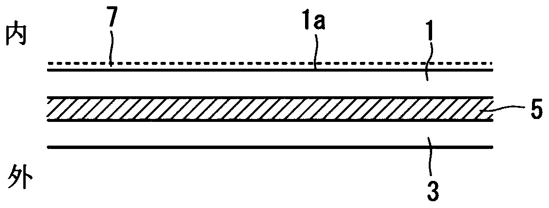
The purpose of the present invention is to provide a blow-moulded container onto which an oil film can be formed without unevenness across the entire inner surface of the container by coating the inner surface with an oil-based liquid. The blow-moulded container thereby exhibits stable lubricity with respect to a contained substance, and is capable of effectively inhibiting the contained substancefrom adhering to the inside of the container and remaining as residue. The blow-moulded container has an inner surface (1a) made of an olefin resin, and is characterised in that said inner surface (1a) uses a medium-chain fatty acid triglyceride as a standard oil, and when 0.8 [mu]l of said standard oil, maintained at 23 DEG C, is dropped, the oil droplet dispersion, defined by the length of themajor axis of a dropped oil droplet, is no less than 5.0mm.

Description

technical field [0001] The present invention relates to blow molded containers provided with an oil film on the inner surface so as to be ready for use. Background technique [0002] Since plastics can be easily formed into various forms in a simple manner, they are widely used in various fields. In particular, olefin-based resins such as low-density polyethylene are used to form the inner surface of the walls of containers such as direct blow molded bottles. Because of its extrudability and extrudability, such direct blow-molded bottles are widely used as containers for containing especially viscous fluid substances such as ketchup and mayonnaise. [0003] Meanwhile, a container for containing a viscous fluid substance needs to have an inner surface showing high sliding properties for the contents so that the contents can be quickly discharged and used up without remaining in the container. [0004] In conventional techniques, slidability is ensured by blending additives ...

Claims


Application Information

Patent Timeline
Patent Type & Authority Applications(China)
IPC IPC(8): B65D1/02B65D65/42
CPCB65D65/42B65D1/0215B65D25/14B65D2231/005B29C2049/023B65D1/02B29C49/06B29L2031/7158B32B27/08B32B27/32B29C2949/302B29C2949/3016
Inventor 阿久津洋介丹生启佑小松威久男
Owner TOYO SEIKAN KAISHA LTD
Learn More