
Special grinding machine for grinding shaft diameter of composite material propeller blade

A composite material and special grinding machine technology, applied in the field of mechanical processing, can solve the problems of not grinding composite material propeller blades, unable to guarantee the roundness and roughness of the shaft diameter, etc.

Inactive Publication Date: 2020-04-14
BAODING XIANGYANG AVIATION PRECISION MACHINERY
View PDF9 Cites 0 Cited by
  • Summary
  • Abstract
  • Description
  • Claims
  • Application Information

AI Technical Summary

Problems solved by technology

The JL4A series composite material propeller blades produced at this stage are composed of fiber structure blades and steel shaft diameters, that is, the blades and shaft diameters are integrated, and the shaft diameters are processed by turning, which cannot guarantee the roundness and roughness of the shaft diameters. Therefore, it must go through the grinding process, but at present there is no special grinder for grinding the shaft diameter of composite propeller blades in China. The traditional grinder can only hold the blade on the headstock, and the thimble of the tailstock withstands the end of the shaft diameter, resulting in grinding During the process, the propeller blade is subjected to torsion and destroys the composite material layer

Method used


Image

  • Special grinding machine for grinding shaft diameter of composite material propeller blade
  • Special grinding machine for grinding shaft diameter of composite material propeller blade
  • Special grinding machine for grinding shaft diameter of composite material propeller blade

Examples


Embodiment Construction

[0018] Below in conjunction with accompanying drawing, the present invention will be further described:

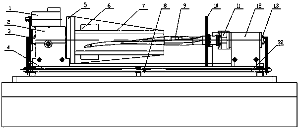
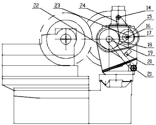
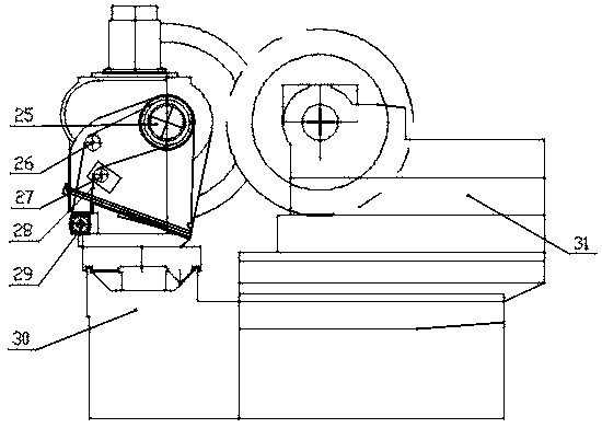
[0019] Such as figure 1 , figure 2 and image 3 As shown, this embodiment includes a MQ1350A universal cylindrical grinding machine bed 30, a motor 1, a headstock box 2, a tailstock box 12, a headstock spindle 3, a tailstock spindle 13, a synchronous linkage device for the headstock and the tailstock, and a propeller blade clamping device 7,

[0020] The head frame box 2 is installed on the front end of the bed 30 of the MQ1350A universal cylindrical grinder, the motor 1 is fixedly installed on the upper side of the head frame box 2 through a bolt assembly, and the output shaft of the motor 1 is connected by a key to install the toothed belt pulley I of the head frame 14. Headstock toothed belt pulley I 14 is connected with headstock toothed belt pulley II 15 through headstock toothed belt III 25, and headstock toothed pulley II 15 is connected with headstock eccentric...


PUM


Abstract

The invention discloses a special grinding machine for grinding the shaft diameter of a composite material propeller blade. The special grinding machine comprises an MQ1350A type universal cylindricalgrinding machine body, a motor, a headstock box body, a tailstock box body, a headstock main shaft, a tailstock main shaft, a headstock and tailstock synchronous linkage device and a propeller bladeclamping device. Power of a headstock is transmitted to a tailstock through the headstock and tailstock synchronous linkage device, so that the composite material propeller blade is prevented from being subjected to torque in the rotating process; the headstock and tailstock synchronous linkage device is composed of a headstock cog belt wheel VI, a cog belt I, a headstock tensioning wheel, a headstock cog belt wheel V, a left polish rod, a polish rod coupler, a right polish rod, a tailstock cog belt wheel III, a tailstock cog belt wheel II, a tailstock tensioning wheel, a tailstock cog belt and a tailstock cog belt wheel I. The turning radius of the grinding machine is increased from 250 mm to 400 mm, so that it is guaranteed that rotation of the maximum-diameter portion of the blade doesnot interfere with the machine tool, meanwhile, it is guaranteed that the composite material propeller blade 9 is not subjected to torque when the shaft diameter is ground, and the blade is preventedfrom being damaged.

Description

technical field [0001] The invention relates to the technical field of mechanical processing, in particular to a special grinder for grinding the shaft diameter of a composite material propeller blade. Background technique [0002] The field of mechanical processing in China is developing at a high speed, and the products are constantly being updated: Among them, the propeller, the main component of the aircraft, is a device that rotates in the air and converts the rotational power of the engine into propulsion or lift. The JL4A series composite material propeller blades produced at this stage are composed of fiber structure blades and steel shaft diameters, that is, the blades and shaft diameters are integrated, and the shaft diameters are processed by turning, which cannot guarantee the roundness and roughness of the shaft diameters. Therefore, it must go through the grinding process, but at present there is no special grinder for grinding the shaft diameter of composite p...

Claims


Application Information

Patent Timeline
Patent Type & Authority Applications(China)
IPC IPC(8): B24B5/04B24B5/35B24B41/06B24B47/12B24B41/02
CPCB24B5/04B24B5/35B24B41/02B24B41/062B24B47/12
Inventor 张雪菲孙博
Owner BAODING XIANGYANG AVIATION PRECISION MACHINERY
Learn More