Device for transmitting encoder signals through optical fiber communication

A technology of optical fiber communication and encoder, which is applied in the field of encoder, can solve the problems that the transmission line is susceptible to electromagnetic interference, the output signal waveform is unstable, and the power supply voltage is reduced, so as to achieve the possibility of reducing interference, short transmission delay, and simple configuration Effect

Pending Publication Date: 2020-04-14
希望森兰科技股份有限公司
View PDF5 Cites 0 Cited by
  • Summary
  • Abstract
  • Description
  • Claims
  • Application Information

AI Technical Summary

Problems solved by technology

Long-distance transmission will cause a large line voltage drop due to the large line resistance, and the encoder power supply voltage will drop, resulting in failure, and the transmission line is susceptible to electromagnetic interf

Method used


Image

  • Device for transmitting encoder signals through optical fiber communication
  • Device for transmitting encoder signals through optical fiber communication

Examples


Example Embodiment

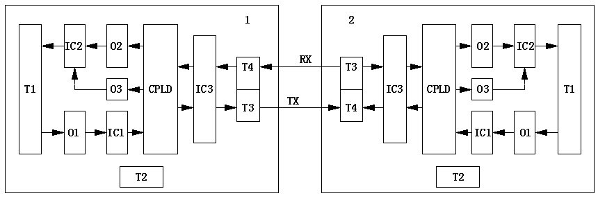
[0015] refer to figure 1 , the present invention is a device for transmitting encoder signals through optical fiber communication. The device has independent and identical encoder signal conversion unit 1 and encoder signal conversion unit 2, hereinafter referred to as conversion unit 1 and conversion unit 2, as well as optical fiber TX and Fiber RX. The hardware of the conversion unit mainly includes optocouplers O1, O2, O3, programmable logic device CPLD, level conversion driver chips IC1, IC2, IC3, and optical fiber socket. The specific implementation is as follows:

[0016] Connect the encoder power supply and output signal cables to terminal T1 of the conversion unit 1. The transmitting fiber base T3 of conversion unit 1 is connected to the receiving fiber base T4 of conversion unit 2 through an optical fiber TX, and the receiving fiber base T4 of conversion unit 1 is connected to the transmitting fiber base T3 of conversion unit 2 through an optical fiber RX. Connect ...


PUM


Abstract

The invention relates to a device for transmitting encoder signals through optical fiber communication, and the device mainly comprises two independent encoder signal conversion units, wherein hardware and software of the encoder signal conversion units are completely consistent. One conversion unit is installed on the side close to the encoder, and the conversion unit converts an encoder electricsignal into communication data and transmits the communication data to the other conversion unit through an optical fiber, and then the conversion unit converts the received communication data into an electric signal which is output by the encoder and is the same as the encoder for standby application. According to the device, encoder output signals are transmitted in an optical fiber communication mode, the anti-interference capability is high, the transmission distance is long, the time delay is short, the cost is low, and the installation is simple.

Description

technical field [0001] The invention relates to the field of encoders, in particular to a device for transmitting encoder signals through optical fiber communication. Background technique [0002] At present, the encoder is widely used as a speed test device, and its output signal is usually directly connected to the PLC, numerical control device, control system, etc. by using a shielded cable. Long-distance transmission will cause a large line voltage drop due to a large line resistance, and the encoder power supply voltage will drop, resulting in failure, and the transmission line is susceptible to electromagnetic interference, resulting in unstable output signal waveforms and reduced accuracy. When using cables to transmit encoder signals, the cable selection and installation specifications have to be considered, which has many disadvantages. Contents of the invention [0003] Aiming at the above requirements and improving the deficiencies of the existing technology, t...

Claims


Application Information

Patent Timeline
IPC IPC(8): H04B10/25
CPCG01P3/00
Inventor 张树林陈万燕郭仕友邓德宽
Owner 希望森兰科技股份有限公司
Why Eureka
Try Eureka