
Husking device

A technology of shell breaking device and shell, which is applied in the direction of shell removal, solid separation, pod removal, etc., can solve the problems of easy loss, time-consuming, inaccurate data analysis, etc., and achieve the effect of convenient packing and ensuring accuracy and integrity.

Pending Publication Date: 2020-04-17
COTTON RES INST HEBEI ACAD OF AGRI & FOREST SCI
View PDF1 Cites 0 Cited by
  • Summary
  • Abstract
  • Description
  • Claims
  • Application Information

AI Technical Summary

Problems solved by technology

[0002] At present, cottonseed shell peeling equipment mainly has three types: disc sheller, blade sheller and magnetic roller sheller, but they are mainly used in the field of cottonseed oil production, such as in the patent number ZL 2014 2 0350091.7 The above-mentioned cotton seed knife roller peeling device adopts a complex mechanical structure to improve the peeling efficiency and the separation degree of kernel shells, but it uses the relative movement of the dynamic knife set and the static knife set to form cutting. On the one hand, it cannot guarantee The integrity of the cottonseed kernel, on the other hand, will generate a certain amount of heat, which will affect the content and physiological activity of the internal components of the cottonseed kernel
[0003] Cottonseed kernels are rich in protein, oil, gossypol, amino acids, vitamins and other components, especially the protein and enzymes in cottonseed are greatly affected by temperature, and are prone to lose part of their activity. The final data analysis is not accurate. The physiological index and component content of the cottonseed kernel are often peeled by manual shearing, which is time-consuming, laborious and easy to hurt hands. Therefore, it is necessary to develop a method that can effectively separate the cottonseed kernel and cottonseed hull, and ensure The integrity of the cottonseed kernel, and the shelling device that does not destroy the internal index components of the cottonseed kernel

Method used


Image

  • Husking device
  • Husking device

Examples


Embodiment Construction

[0027] The present invention will be further described below in conjunction with the accompanying drawings.

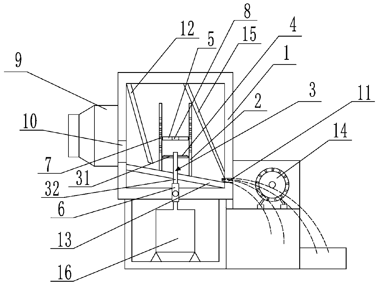
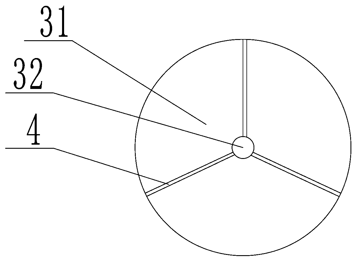
[0028] as attached Figure 1-2 As shown, the present embodiment provides a peeling device, which includes a housing 1, a separation cylinder 2 arranged inside the housing 1, a shell breaking device arranged inside the separation cylinder 2, and a shell breaking device connected with the shell breaking device. The drive motor 16 connected to the device, the cracking device includes a knife rest 3 arranged inside the separation cylinder 2 and more than one blade 4 arranged on the knife rest 3, and more than one separation blade 4 is arranged on the separation cylinder 2. Hole 7, the aperture of the separation hole 7 is 4.8 ~ 5.6mm, the design principle of the aperture size of the separation hole 7 is that the cottonseed shell and cottonseed kernel after the shell can only pass through the separation hole 7, and the whole cottonseed that has not been peeled off cannot pas...


PUM


Abstract

The invention provides a husking device comprising a shell, a separating cylinder arranged in the shell, a shell breaking device arranged in the separating cylinder and a driving motor connected withthe shell breaking device. The shell breaking device comprises a knife rest arranged in the separating cylinder and more than one blade arranged on the knife rest; a material pressing cover is movablyarranged above the knife rest; and the knife rest is connected with a driving shaft of the driving motor through a coupler. The knife rest includes a knife disc and a knife shaft fixedly connected with the knife disc. The blades are obliquely arranged on the knife disc; more than one notch is formed in the knife disc; and the blades are clamped at the notches. More than one separation hole is formed in the separating cylinder; and a charge hole is formed in the material pressing cover. Therefore, the cottonseed kernel and the cottonseed hull are separated effectively and the cottonseed kernelis protected from being damaged; and the internal index components of the cottonseed kernel are not damaged.

Description

technical field [0001] The invention relates to a crop processing device, in particular to a peeling device. Background technique [0002] At present, cottonseed shell peeling equipment mainly has three types: disc sheller, blade sheller and magnetic roller sheller, but they are mainly used in the field of cottonseed oil production, such as in the patent number ZL 2014 2 0350091.7 The above-mentioned cotton seed knife roller peeling device adopts a complex mechanical structure to improve the peeling efficiency and the separation degree of kernel shells, but it uses the relative movement of the dynamic knife set and the static knife set to form cutting. On the one hand, it cannot guarantee The integrity of the cottonseed kernel, on the other hand, will generate a certain amount of heat, which will affect the content and physiological activity of the internal components of the cottonseed kernel. [0003] Cottonseed kernels are rich in protein, oil, gossypol, amino acids, vita...

Claims


Application Information

Patent Timeline
IPC IPC(8): A23N5/00B07B15/00
CPCA23N5/00B07B15/00
Inventor 王广恩李俊兰崔淑芳钱玉源刘祎金卫平闵卓张曦米换房段世贞车亮
Owner COTTON RES INST HEBEI ACAD OF AGRI & FOREST SCI
Learn More