Electroforming composite material and preparation method thereof
A composite material and composite material layer technology, applied in the field of electroforming composite materials and their preparation, can solve the problems of easy peeling off of the coating, poor material surface quality, unfavorable environmental protection, etc., and achieve the effect of reducing the difficulty of preparation and improving the qualified rate
- Summary
- Abstract
- Description
- Claims
- Application Information
AI Technical Summary
Problems solved by technology
Method used
Image

Examples
Embodiment 1
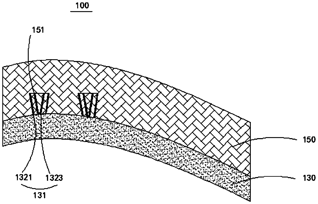
[0040] figure 1 Schematic diagram of the structure of the electroformed composite material provided for Example 1 of the present invention; please refer to figure 1 .
[0041] The electroplating composite material 100 provided in this embodiment includes a stacked metal layer 130 and a composite material layer 150. The composite material layer 150 is formed of a carbon fiber composite material. The metal layer 130 deposits a connecting portion 131 toward the surface of the composite material layer 150. The composite material The surface of the layer 150 facing the metal layer 130 has a connection groove 151 at a position corresponding to the connection portion 131 , and the connection portion 131 is located in the connection groove 151 , so that the metal layer 130 and the composite material layer 150 are fixedly connected.
[0042] The metal layer 130 is made of various materials, such as nickel, iron, and copper. In this embodiment, the metal layer 130 is made of nickel. ...
Embodiment 2
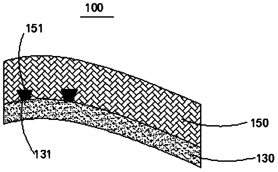
[0048] image 3 Schematic diagram of the structure of the electroformed composite material provided for Example 2 of the present invention; please refer to image 3 .
[0049] The electroplating composite material 100 provided in this embodiment includes a stacked metal layer 130 and a composite material layer 150. The composite material layer 150 is formed of a carbon fiber composite material. The metal layer 130 deposits a connecting portion 131 toward the surface of the composite material layer 150. The composite material The surface of the layer 150 facing the metal layer 130 has a connection groove 151 at a position corresponding to the connection portion 131 , and the connection portion 131 is located in the connection groove 151 , so that the metal layer 130 and the composite material layer 150 are fixedly connected.
[0050] The metal layer 130 is made of various materials, such as nickel, iron, and copper. In this embodiment, the metal layer 130 is made of nickel. ...
Embodiment 3
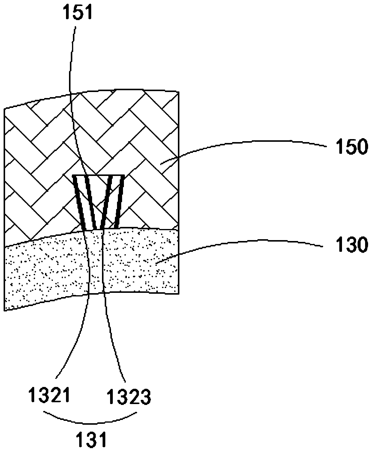
[0059] This embodiment provides an electroformed composite material, which has a structure similar to that of the electroformed composite material in Embodiment 2, except that the connection part of the electroformed composite material provided by this embodiment is in the shape of a barb.
[0060] Figure 5 For the enlarged structural schematic diagram of the connection part of the electroformed composite material provided in Example 3 of the present invention, please refer to Figure 5 .
[0061] The connecting portion 131 is in the shape of a barb. The connecting portion 131 includes a straight section 1311 and a bent section 1313. The straight section 1311 is vertically deposited on the surface of the metal layer 130, and the bent section 1313 is fixedly connected to the surface of the straight section 1311 away from the metal layer 130. At one end, the shape of the connecting groove 151 matches the shape of the connecting portion 131 .
[0062] The straight section 1311...
PUM
| Property | Measurement | Unit |
|---|---|---|
| Thickness | aaaaa | aaaaa |
Abstract
Description
Claims
Application Information
 - R&D
- Intellectual Property
- Life Sciences
- Materials
- Tech Scout
- Unparalleled Data Quality
- Higher Quality Content
- 60% Fewer Hallucinations
Browse by: Latest US Patents, China's latest patents, Technical Efficacy Thesaurus, Application Domain, Technology Topic, Popular Technical Reports.
© 2025 PatSnap. All rights reserved.Legal|Privacy policy|Modern Slavery Act Transparency Statement|Sitemap|About US| Contact US: help@patsnap.com