Flame blowing method and flame blowing system
A flame and natural gas technology, applied in glass manufacturing equipment, manufacturing tools, etc., can solve the problems of low energy utilization, high heat consumption, large initial investment, etc., and achieve the effects of reducing heat loss, sufficient combustion, and reducing energy consumption
- Summary
- Abstract
- Description
- Claims
- Application Information
AI Technical Summary
Problems solved by technology
Method used
Image
Examples
Embodiment 1
[0049] Preparation of glass microfibers with a heat-resistant temperature of 600°C
[0050] Ingredients:
[0051] composition SiO 2
al 2 o 3
Fe 2 o 3
MgO B 2 o 3
TiO 2
content(%) 60.0 20.0 8.0 8.0 2.0 2.0
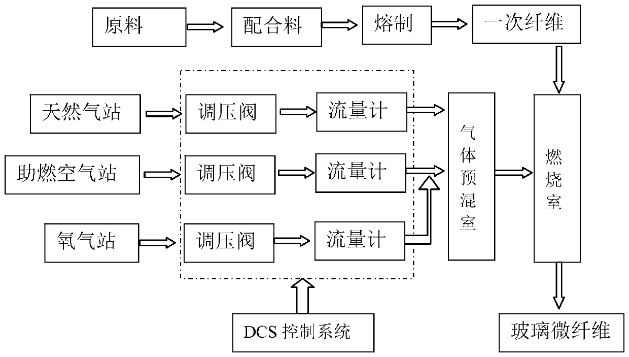
[0052] see figure 2 According to the formula requirements, it is formulated into glass batch materials, put into the pool kiln for melting, the melting temperature is controlled at 1550°C±20°C, and the mixed heating method of electrodes and flames is used in the forehearth to form glass liquid with stable temperature and good homogenization. To the leak plate; the melted glass passes through the leak plate and the leak nozzle, and is drawn by the rubber roller drawing machine to form a primary fiber with a diameter of 100-300 μm, and then is sent to the injection port of the combustion chamber through the guide mechanism, where Melted and stretched to the required size (average diameter 1.5-2.0 microns), form...
Embodiment 2
[0057] Preparation of glass microfibers with a heat-resistant temperature of 600°C
[0058] Ingredients:
[0059] composition SiO 2
al 2 o 3
Fe 2 o 3
MgO B 2 o 3
TiO 2
content(%) 60.0 20.0 8.0 8.0 2.0 2.0
[0060] see figure 2 According to the formula requirements, it is formulated into glass batch materials, put into the pool kiln for melting, the melting temperature is controlled at 1550°C±20°C, and the mixed heating method of electrodes and flames is used in the forehearth to form glass liquid with stable temperature and good homogenization. To the leak plate; the melted glass passes through the leak plate and the leak nozzle, and is drawn by the rubber roller drawing machine to form a primary fiber with a diameter of 100-300 μm, and then is sent to the injection port of the combustion chamber through the guide mechanism, where Melted and stretched to the required size (average diameter 1.5-2.0 microns), form...
Embodiment 3
[0065] Preparation of glass microfibers with a heat-resistant temperature of 650°C
[0066] Ingredients:
[0067] composition SiO 2
al 2 o 3
MgO B 2 o 3
TiO 2
content(%) 65.0 23.0 8.0 2.0 2.0
[0068] see figure 2 According to the formula requirements, it is formulated into glass batch materials, put into the pool kiln for melting, and the melting temperature is controlled at 1570°C±20°C. The mixed heating method of electrodes and flames is used in the forehearth to form glass liquid with stable temperature and good homogenization. To the leak plate; the melted glass passes through the leak plate and the leak nozzle, and is drawn by the rubber roller drawing machine to form a primary fiber with a diameter of 100-300 μm, and then is sent to the injection port of the combustion chamber through the guide mechanism, where Melted and stretched to the required size (average diameter 1.5-2.0 microns), forming glass microfibers....
PUM
| Property | Measurement | Unit |
|---|---|---|
| diameter | aaaaa | aaaaa |
| diameter | aaaaa | aaaaa |
| thermal resistance | aaaaa | aaaaa |
Abstract
Description
Claims
Application Information
 - R&D
- Intellectual Property
- Life Sciences
- Materials
- Tech Scout
- Unparalleled Data Quality
- Higher Quality Content
- 60% Fewer Hallucinations
Browse by: Latest US Patents, China's latest patents, Technical Efficacy Thesaurus, Application Domain, Technology Topic, Popular Technical Reports.
© 2025 PatSnap. All rights reserved.Legal|Privacy policy|Modern Slavery Act Transparency Statement|Sitemap|About US| Contact US: help@patsnap.com


