Energy-saving aluminum electrolyzer
An aluminum electrolytic cell and energy-saving technology, which is applied in the field of electrolytic aluminum equipment, can solve the problems of collecting exhaust pipes and forced ventilation flue design and complex engineering, and achieve good energy-saving benefits, strong practicability, and improved gas collection efficiency. Effect
- Summary
- Abstract
- Description
- Claims
- Application Information
AI Technical Summary
Problems solved by technology
Method used
Image
Examples
Embodiment 1
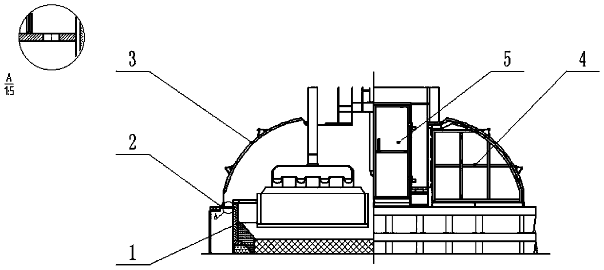
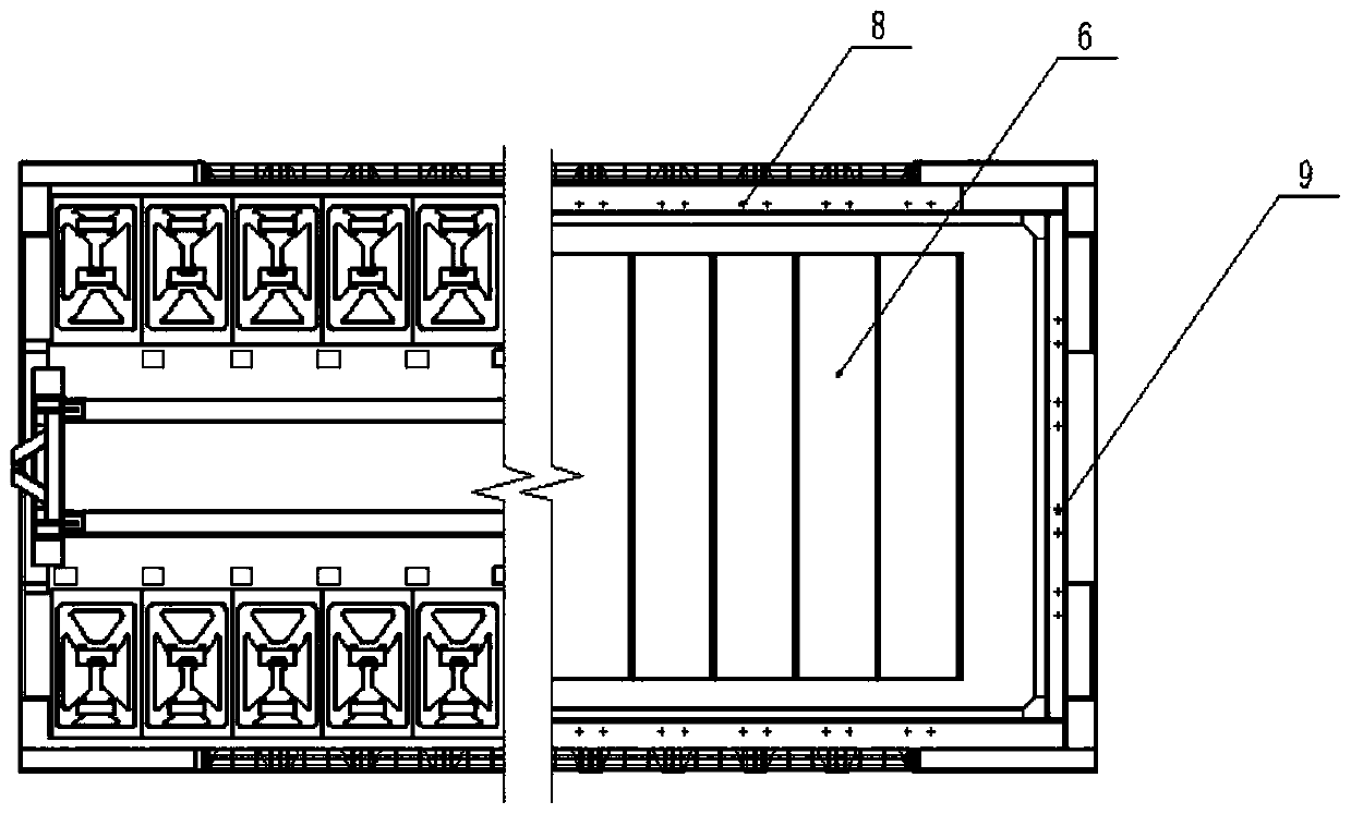
[0023] Such as Figure 1-2 As shown, an energy-saving aluminum electrolytic cell adopts a 400KA electrolytic cell, including a tank shell 1, a tank shell coaming plate 2, a tank cover plate 3, an end face angle plate 4 and a furnace door 5, and the tank shell coaming plate 2 is provided with several Two circular heat dissipation holes, divided into horizontal heat dissipation holes 8 and longitudinal heat dissipation holes 9, the hole diameter is 5cm, every two horizontal heat dissipation holes 8 correspond to a group of cathodes 6, and the bottom of the slot cover plate 3 is placed in the middle of the slot shell enclosure plate 2 In the external position, cover the 8 holes of the horizontal shroud for heat dissipation in the space in the tank, set the end face angle plate 4 on the plane where the furnace door 5 is located, and cover the cooling holes 9 of the longitudinal shroud in the space in the tank, and the tank shell 1 can be an integrated cradle tank The shell can als...
Embodiment 2
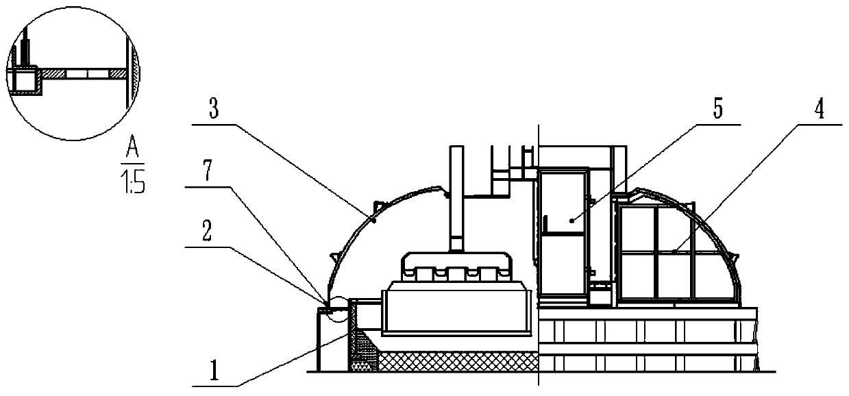
[0026] Such as Figure 3-4 As shown, an energy-saving aluminum electrolytic cell adopts a 500KA electrolytic cell, including a tank shell 1, a tank shell coaming plate 2, a tank cover plate 3, an end face angle plate 4 and a furnace door 5, and the tank shell coaming plate 2 is provided with several A long-hole-shaped cooling hole with a radius of 5 cm and a center length of 20 cm is divided into a horizontal cooling hole 8 and a vertical cooling hole 9, and each slot-shaped horizontal cooling hole 8 corresponds to a group of cathodes 6, and a cover is provided outside the tank shell enclosure 2. Plate support device 7, the bottom of the tank cover plate 3 is placed on the cover plate support device 7 outside the tank shell coaming plate 2, and the horizontal coaming plate is radiated, 8 is covered in the space in the tank, and the end face angle plate 4 is set on the plane where the furnace door 5 is located , cover the cooling hole 9 of the longitudinal shroud in the space i...
Embodiment 3
[0029] The heat dissipation holes of the shroud in the embodiment are round holes with a diameter of 20 cm, and the others are the same as in Embodiment 2.
[0030] Embodiment: The air naturally cooled by the side of the tank shell 1 enters the tank cover plate 3 through the heat dissipation holes of the coaming plate, and enters the flue gas purification system together with the gas generated by the reaction in the tank, so that part of the heat radiated from the side is transferred To the furnace surface in the tank, overcome a large amount of cold air to take away the heat, ensure that the electrolytic tank can have a certain degree of superheat under low voltage, the production runs smoothly, the voltage is reduced by 241mv; the flue gas volume of a single tank is reduced by 35%; the ton of aluminum saves 850kWh, Realize the goal of substantial energy saving.
PUM
| Property | Measurement | Unit |
|---|---|---|
| diameter | aaaaa | aaaaa |
| radius | aaaaa | aaaaa |
Abstract
Description
Claims
Application Information
 - R&D
- Intellectual Property
- Life Sciences
- Materials
- Tech Scout
- Unparalleled Data Quality
- Higher Quality Content
- 60% Fewer Hallucinations
Browse by: Latest US Patents, China's latest patents, Technical Efficacy Thesaurus, Application Domain, Technology Topic, Popular Technical Reports.
© 2025 PatSnap. All rights reserved.Legal|Privacy policy|Modern Slavery Act Transparency Statement|Sitemap|About US| Contact US: help@patsnap.com


