
Equipment for solving oil-gas separation in engine cylinder head remanufacturing process

A technology for engine cylinder head and separation equipment, which is applied to mechanical equipment, engine components, machines/engines, etc., can solve the problems of slow separation speed and general effect, and achieves increased selectivity, strong practicability, and wide application range. Effect

Inactive Publication Date: 2020-04-17
WUHU DINGHAN REMFR TECH
View PDF8 Cites 0 Cited by
  • Summary
  • Abstract
  • Description
  • Claims
  • Application Information

AI Technical Summary

Problems solved by technology

[0003] In order to simplify the structure, many engines now choose to design and install a baffle-type oil-air separator on the cylinder head under the condition of meeting the emission conditions, so that the crankcase ventilation can be integrated on the cylinder head; the baffle-type oil-air separator is also It is vividly called a labyrinth oil-gas separator. Its working principle is to install cross-cut partitions in the flow direction of the airflow to block the mixed gas. It is separated from the mixture under the action of impact. Due to the simple structure, the separation effect is average and the separation speed is relatively slow.

Method used


Image

  • Equipment for solving oil-gas separation in engine cylinder head remanufacturing process
  • Equipment for solving oil-gas separation in engine cylinder head remanufacturing process
  • Equipment for solving oil-gas separation in engine cylinder head remanufacturing process

Examples


Embodiment Construction

[0021] In order to enable those skilled in the art to better understand the technical solutions of the present invention, the present invention will be described more clearly and completely below in conjunction with the accompanying drawings in the embodiments. Of course, the described embodiments are only a part of the present invention. Not all, based on this embodiment, other embodiments obtained by those skilled in the art without creative efforts are all within the protection scope of the present invention.

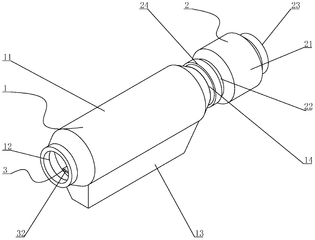
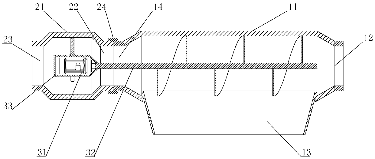
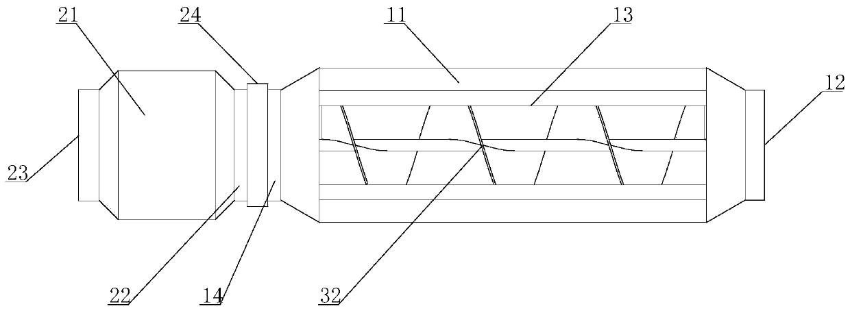
[0022] Such as Figure 1 to Figure 3 As shown, a kind of oil-gas separation equipment in the process of remanufacturing the engine cylinder head includes a separation chamber 1, and the internal rotation of the separation chamber 1 is provided with a spiral separation assembly 3 for rapid extraction and separation of oil and gas. The rotating spiral separation assembly 3 not only sucks the mixed oil and gas from a distance, increases the extraction, improves the proc...


PUM


Abstract

The invention relates to equipment for solving oil-gas separation in an engine cylinder head remanufacturing process. The equipment comprises a separation bin, and a spiral separation assembly is rotationally arranged in the separation bin and used for performing rapid extraction and separation on oil and gas. A baffle in an original baffle type oil-gas separator is changed into a spiral blade, and the separation bin is set to be in a round tube shape, so that mixed oil and gas can enter the static spiral blade from an inlet at a normal speed and move along the spiral blade to be separated bythe normal baffle type oil-gas separator. The equipment can also increase the original suction speed of the mixed oil and gas by the rotating spiral blade, so that the entering speed of the mixed oiland gas is increased, and the rotating spiral blade can separate oil from gas more efficiently and quickly by centrifugal force; and oil-gas separation of the mixed oil and gas can be performed eitherin the traditional baffle type oil-gas separator manner or in the centrifugal force manner, and the selectivity is improved.

Description

technical field [0001] The invention relates to the field of remanufacturing, in particular to an oil-gas separation device in the process of remanufacturing engine cylinder heads. Background technique [0002] The oil-air separator is the main component of the crankcase ventilation system, which efficiently separates the oil in the crankcase blow-by gas, and its separation performance has an important impact on the reliability and emission of the engine; when the engine is running normally, the oil in the cylinder There will be a part of unburned combustible mixture and combustion exhaust gas entering the crankcase through three ways: 1) Piston ring end clearance, piston ring and cylinder clearance, and piston ring and ring groove clearance; 2) Valve and valve guide clearance; 3 ) Supercharger bearing clearance; these blow-by gases will increase the temperature in the crankcase and increase the evaporation of oil in the oil pan. [0003] In order to simplify the structure,...

Claims


Application Information

Patent Timeline
Patent Type & Authority Applications(China)
IPC IPC(8): F01M13/04
CPCF01M13/04F01M2013/0422
Inventor 程敬卿王蓉蓉刘丽艳
Owner WUHU DINGHAN REMFR TECH
Learn More