Road pipeline burying assembly, pipeline burying method, and production device and method of pipeline burying assembly

A technology of pipe components and roads, which is applied in the direction of roads, roads, pipeline laying and maintenance, etc., can solve the problems affecting the integrity of the service life of the road surface, can not achieve effective management, and the iron plate is not conducive to the driving of vehicles, etc., to ensure the use of Longevity, rapid installation, and the effect of improving the service life

Pending Publication Date: 2020-04-17
成都九执星科技有限公司
View PDF0 Cites 2 Cited by
  • Summary
  • Abstract
  • Description
  • Claims
  • Application Information

AI Technical Summary

Problems solved by technology

However, in the actual construction of municipal infrastructure projects, sometimes it is often necessary to slot the road surface to realize the landfill and layout of the pipeline. The components or devices for effective management of the opened grooves lead to poor management of small width grooves in the current road construction process, especially for grooves with a width of less than 20cm, which cannot be effectively managed, resulting in the road being opened. The groove affects the integrity of the service life of the road surface. In addition, in the prior art, an iron plate is often covered above the groove to ensure road communication, but the iron plate is not conducive to the driving of vehicles.

Method used


Image

  • Road pipeline burying assembly, pipeline burying method, and production device and method of pipeline burying assembly
  • Road pipeline burying assembly, pipeline burying method, and production device and method of pipeline burying assembly
  • Road pipeline burying assembly, pipeline burying method, and production device and method of pipeline burying assembly

Examples


Embodiment 1

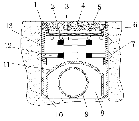
[0035] As shown in the drawings, a road buried pipe assembly of the present invention includes a filling structure, a support groove structure and a protective cover 11; a buried pipe groove 8 is opened on the road and the pipe body 9 is placed in the buried pipe groove 8 to protect The cover 11 is used to cover the top of the pipe body 9, the support groove structure is located above the protective cover 11 and is used to press against the side wall of the tank body, the filling structure is arranged above the support groove structure and its upper surface is flush with the ground;

[0036] The filling structure includes a supporting mold 1 and a filling layer 4. An upwardly opening filling groove is arranged on the inner side of the supporting mold 1, and a grid supporting layer 5 integrally formed with the supporting mold 1 is arranged at the bottom of the filling groove. The grid supporting layer 5 is in the shape of a cross grid, and a filling layer 4 is arranged in the fi...

Embodiment 2

[0044] The buried pipe method of the buried pipe assembly in embodiment 1 may further comprise the steps:

[0045] Step 1: Plan the slotting path on the road surface, divide the slotting path into sections with a length of 5-8m, and set up buried pipe grooves 8 on the road surface in sequence according to the segmentation sequence on the road surface; the depth of buried pipe groove 8 is the pre-buried Twice the diameter of the pipeline body 9, and the depth is 1.5-3 times the diameter of the embedded pipeline body 9;

[0046] Step 2: Put the pipe body 9 into the buried pipe groove 8, cover the protective cover 11 above the pipe body 9, then adjust the rotating sleeve 3 to shorten the distance between the two pressing plates 13, and place the The support groove structure is put into the buried pipe groove 8;

[0047] Step 3: draw lines on the side walls of both sides of the buried pipe groove 8, and the distance between the drawn line position and the ground is 4-6cm; draw th...

Embodiment 3

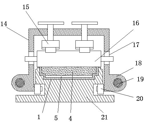
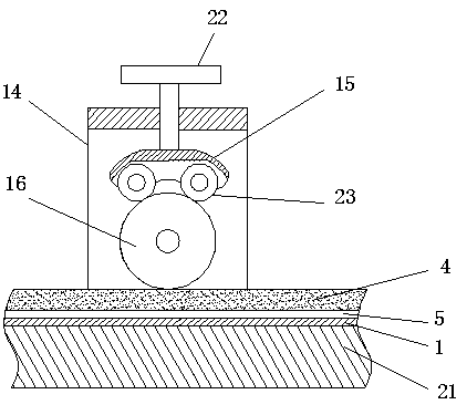
[0050] The production device of the filling structure in embodiment 1: comprises pallet 21, gantry 14, pressurization mechanism, extrusion roller 16 and transmission mechanism, and pallet 21 top is provided with the mold groove that cooperates supporting mold 1 to place, and supports The upper part of the mold 1 is flush with the notch of the mold groove; the two sides of the pallet 21 are provided with chute respectively, the portal frame 14 is covered on the pallet 21, and the inner side of the lower part of the portal frame 14 is respectively connected with a pulley 20 , the gantry 14 presses against the chute by pressing the pulley 20 and moves along the chute; the arms on the left and right sides of the gantry 14 are provided with vertical waist-shaped holes 17, and the extrusion rollers 16 are horizontally arranged on the The inner side of the portal frame 14 and its two ends penetrate in the waist-shaped hole 17 to limit its extrusion roller 16; Outside the lower part, ...


PUM


Abstract

The invention relates to a road pipeline burying assembly, a pipeline burying method and a production device and method of the pipeline burying assembly, and belongs to the technical field of municipal road construction, in particular to the field of pipeline construction or layout in a road. The road pipeline burying assembly comprises a filling structure, a groove supporting structure and a protective cove, wherein a pipeline burying groove is formed in the road, a pipeline body is arranged the rear part of the pipeline burying groove, the protective cover is used for covering parts above the pipeline body, the groove supporting structure is located above the protective cover and is used for tightly abutting against the side wall of a groove body, the filling structure is arranged abovethe groove supporting structure, and the upper surface of the groove supporting structure is flush with the ground. Backfilling management is carried out on the groove less than 20 cm formed in the road surface, so that it is guaranteed that the road surface is normally used after grooving is carried out; and the pipe burying groove formed in the road surface is filled, and the groove supporting structure is used for external force intervention of stress in the side walls of the two sides of the pipe burying groove, so that the problem that the road surface is deformed due to the fact that thetwo sides of the pipe burying groove extrudes the interior of the groove when a vehicle travels is solved, and the service life of the road surface after grooving is carried out is guaranteed.

Description

technical field [0001] The invention relates to a road buried pipe component, a buried pipe method, and a production device and method for the buried pipe component, belonging to the technical field of municipal road construction, in particular to the field of pipeline construction or layout in roads. Background technique [0002] In order to adapt to the influence of traffic and natural factors, pavement engineering uses various road construction materials to build multi-layered solid, stable, flat and certain roughness roads within the range of the roadway on the subgrade. Its structure is generally composed of surface layer, base layer (load-bearing layer) and cushion layer, and the surface should be made into a road arch to facilitate drainage. However, in the actual construction of municipal infrastructure projects, sometimes it is often necessary to slot the road surface to realize the landfill and layout of the pipeline. The components or devices for effective manage...

Claims


Application Information

Patent Timeline
Patent Type & Authority Applications(China)
IPC IPC(8): F16L1/11F16L1/028F16L57/00E02D29/045E02D17/08E01C9/00
CPCE01C9/00E02D17/08E02D17/083E02D29/10F16L1/028F16L1/11F16L57/00
Inventor 曾世涛
Owner 成都九执星科技有限公司
Why Eureka
Try Eureka