Arch-shaped self-oxygen-supply waste heat utilization type direct methanol fuel cell

A methanol fuel cell and methanol fuel technology, applied in fuel cells, fuel cell additives, fuel cell heat exchange, etc., can solve the problems of hindering the reaction, increasing the volume of the system, and increasing the difficulty of battery management, so as to reduce the overall cost, extended working hours, and the effect of ensuring operability and controllability

Active Publication Date: 2020-04-17
SOUTH CHINA UNIV OF TECH
View PDF4 Cites 0 Cited by
  • Summary
  • Abstract
  • Description
  • Claims
  • Application Information

AI Technical Summary

Problems solved by technology

Water droplets cover and block the cathode flow field plate, so that oxygen cannot continue to pass through the cathode flow field plate to reach the membrane electrode, which seriously hinders the progress of the reaction
[0009] In order to solve the problem of the mutual influence of methanol and water evaporation in Guo and Faghri's scheme, Jewett et al. in the literature Gregory Jewett, Zhen Guo, Amir Faghri.Performance characteristics of vapor feed passive miniature direct methanol fuel cell[J].InternationalJournal of Heat and Mass Transfer,2009,52(19-20). The above feeding mechanism was optimized. They separated water and methanol into two fuel tanks for storage, and then exported them to the evaporation area with capillary wicks respectively. The optimized system can Actively control the ratio of fuel to control the output of the battery, but this design will undoubtedly increase the volume of the system and increase the difficulty of battery management

Method used


Image

  • Arch-shaped self-oxygen-supply waste heat utilization type direct methanol fuel cell
  • Arch-shaped self-oxygen-supply waste heat utilization type direct methanol fuel cell
  • Arch-shaped self-oxygen-supply waste heat utilization type direct methanol fuel cell

Examples


Embodiment Construction

[0040] In order to further understand the present invention, the present invention will be further described below in conjunction with the accompanying drawings and examples, but it should be noted that the protection scope of the present invention is not limited to the scope expressed in the examples.

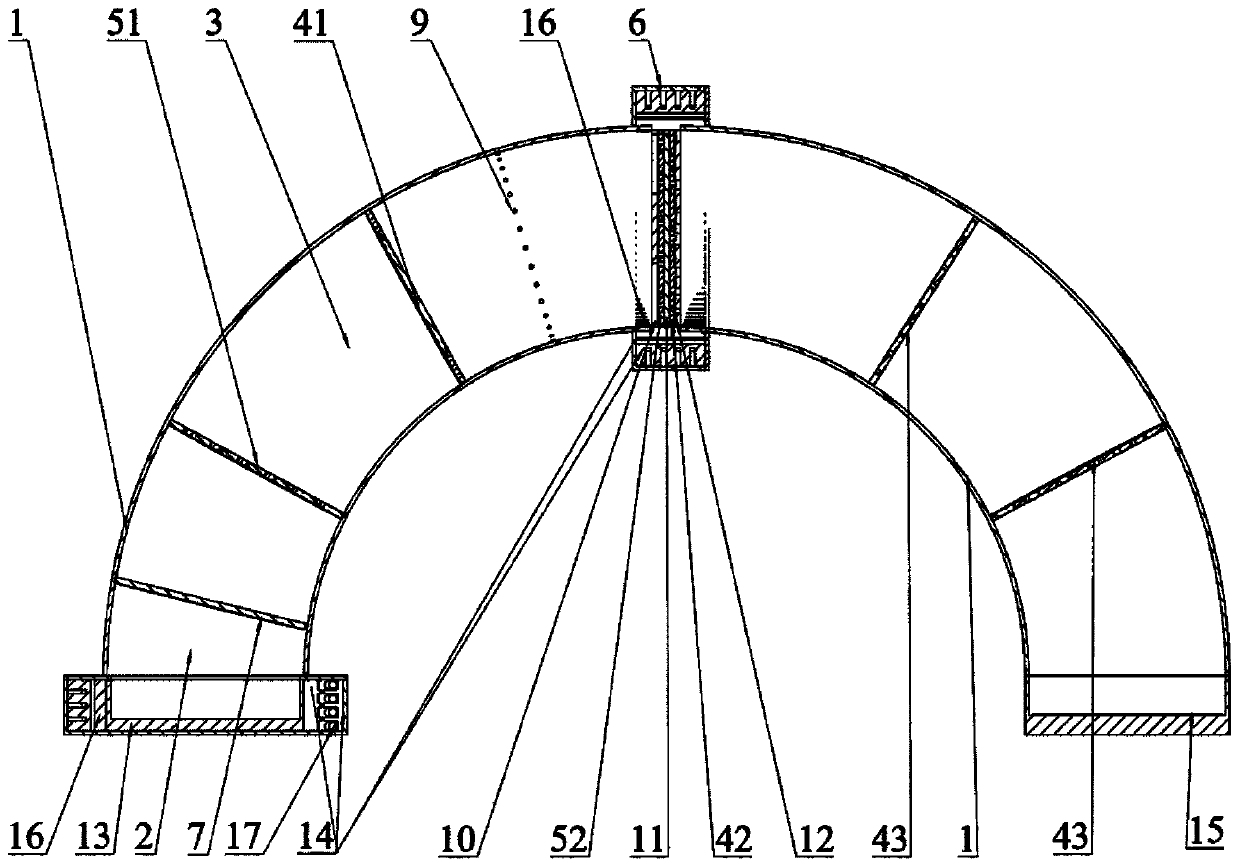
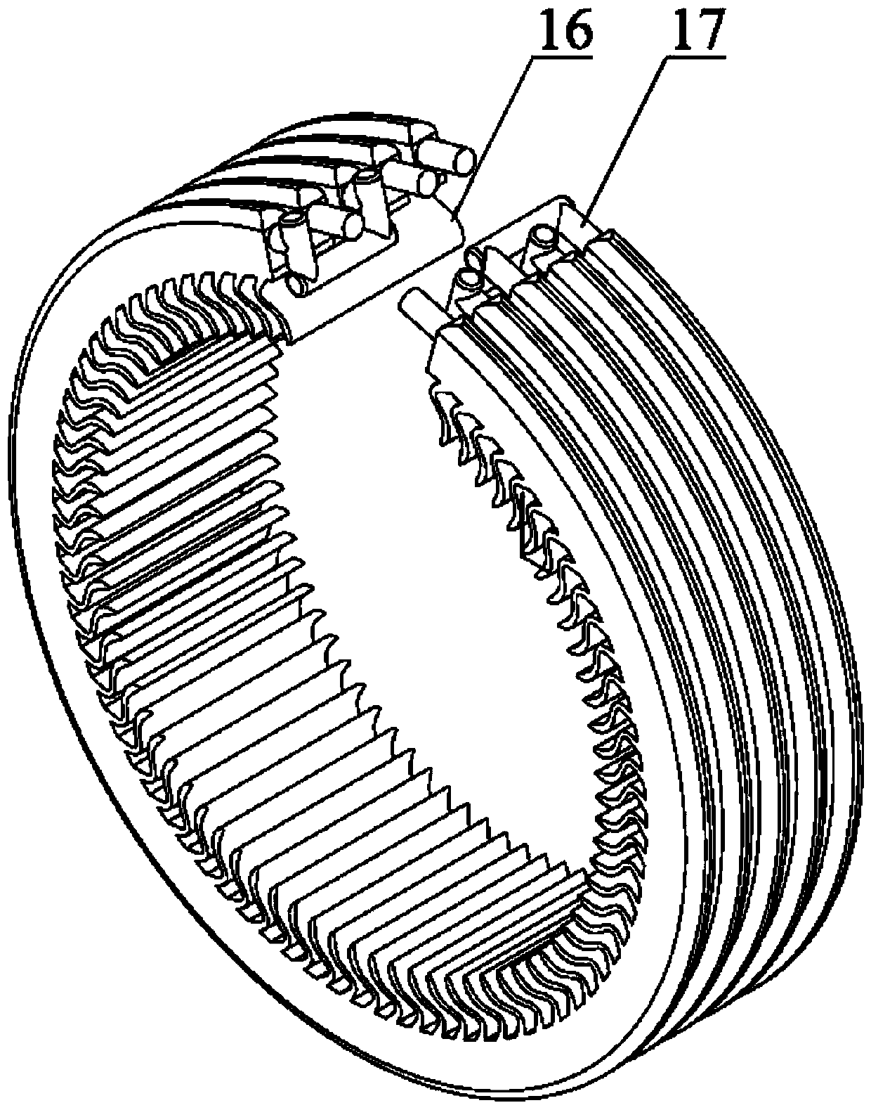
[0041] Such as figure 1 and figure 2 As shown, an arched self-supplied oxygen waste heat utilization type direct methanol fuel cell includes an arched shell 1, a pervaporation membrane 7, a central reaction part, an oxygen generation chamber 15 and a thermodynamic cycle system 14; the pervaporation membrane 7 Divide the arched shell 1 into a methanol fuel chamber 2 and a steam chamber 3;

[0042] The arched housing 1 is mainly formed by connecting two quarter ring pipes made of epoxy resin, which ensures the visualization of the fuel cell reaction, and the ring pipe also ensures The basic dimensions are defined, such as methanol fuel chamber 2, pervaporation membrane 7, hyd...


PUM

PropertyMeasurementUnit
thicknessaaaaaaaaaa
particle diameteraaaaaaaaaa
thicknessaaaaaaaaaa

Abstract

The invention discloses an arch-shaped self-oxygen-supply waste heat utilization type direct methanol fuel cell comprising an arch-shaped shell, a pervaporation membrane, a central reaction part, an oxygen generation cavity and a thermodynamic cycle system. The arched shell is divided into a methanol fuel cavity and a steam cavity by the pervaporation membrane; a gas buffer structure is arranged in the steam cavity; the gas buffer structure comprises a first hydrophobic fiberboard and a first hydrophilic porous board arranged at an interval with the first hydrophobic fiberboard; the central reaction part is provided with an anode flow field plate, a membrane electrode and a cathode flow field plate, the membrane electrode is located between the anode flow field plate and the cathode flow field plate, and a second hydrophilic porous board is arranged between the anode flow field plate and the anode side of the membrane electrode; a second hydrophobic fiberboard is arranged between the cathode side of the membrane electrode and the cathode flow field plate; and the oxygen generation cavity is provided with a double-layer third hydrophobic fiberboard. The energy density of the cell iseffectively improved, and high-concentration methanol and even pure methanol supply of the cell is realized and thus the working time of the cell is prolonged.

Description

technical field [0001] The invention relates to the technical field of fuel cells, in particular to an arch-type direct methanol fuel cell for self-supplying oxygen and waste heat utilization. Background technique [0002] Vapor-passive direct methanol fuel cell (V-DMFC) is a form of direct methanol fuel cell. Because of its higher energy density, weaker methanol breakthrough phenomenon, and longer working time, it has wider development and research value, but the steam supply method and reasonable management methods of V-DMFC are the key factors to inhibit the overall development of V-DMFC. The key factor for the enhanced performance, especially for the realization of pure methanol feed to V-DMFC, which appears to be particularly important. [0003] The electrode and cell reactions of a direct methanol fuel cell are as follows: [0004] The anode reaction is CH 3 OH+H 2 O→6H + +6e - +CO 2 [0005] The cathode reaction is 3 / 2O 2 +6H + +6e - →3H 2 o [0006] The ...

Claims


Application Information

Patent Timeline
Patent Type & Authority Applications(China)
IPC IPC(8): H01M8/1011H01M8/04089H01M8/023H01M8/1018H01M8/04007
CPCH01M8/1011H01M8/04089H01M8/023H01M8/1018H01M8/04007Y02E60/50
Inventor 袁伟郑天翔苏晓晴李嘉毅徐晓林庄梓译卢彪武
Owner SOUTH CHINA UNIV OF TECH
Why Eureka
Try Eureka