Electric vehicle permanent magnet synchronous motor torque control method

A permanent magnet synchronous motor and torque control technology, which is applied in motor generator control, single motor speed/torque control, electronic commutation motor control, etc., can solve the problems of not being able to keep up in time, battery voltage drop, and violation of accuracy requirements and other problems, to achieve the effect of fast response, satisfying stability, and fast torque accuracy

Inactive Publication Date: 2020-04-17
WUHAN MARINE ELECTRIC PROPULSION RES INST CHINA SHIPBUILDING IND CORP NO 712 INST
View PDF3 Cites 10 Cited by
  • Summary
  • Abstract
  • Description
  • Claims
  • Application Information

AI Technical Summary

Problems solved by technology

[0005] This method can not only optimize the efficiency, but also solve the problems of system stability and magnetic field weakening, but there is a defect, the table regards the DC bus voltage as a fixed voltage and the speed as a fixed speed in the look-up table , but in the actual process, the DC bus voltage is the battery voltage. The battery voltage changes during the running of the car, and the speed also changes. When the torque is quickly responded to, it may cause the speed to rise rapidly and the battery voltage to drop. It is easy to appear that the voltage is saturated during the dynamic adjustment process and the look-up table method cannot keep up with it in time, because the look-up table method filters the signal, and there must be errors in the DC bus voltage detection, which will cause the motor to be saturated in voltage....

Method used


Image

  • Electric vehicle permanent magnet synchronous motor torque control method
  • Electric vehicle permanent magnet synchronous motor torque control method
  • Electric vehicle permanent magnet synchronous motor torque control method

Examples


Embodiment Construction

[0029] The present invention will be described in further detail below in conjunction with the accompanying drawings.

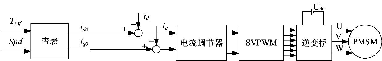
[0030] Step 1, calibrate the rotational speed point of the permanent magnet synchronous motor.

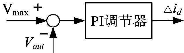
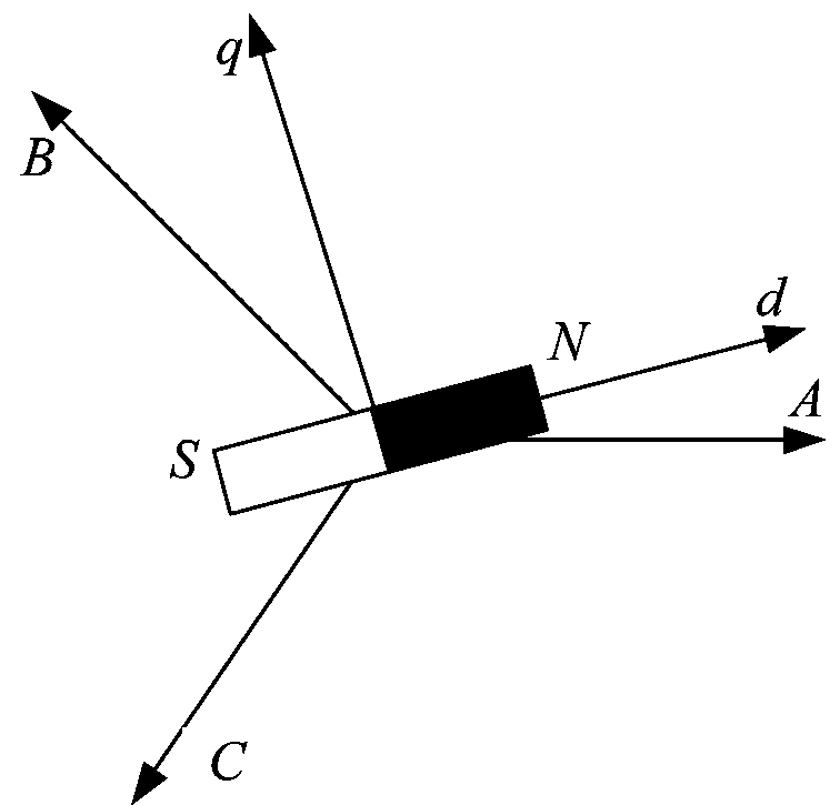
[0031] Adjust the angle between the D-axis current and the Q-axis current at the same current amplitude, so that the output motor torque reaches the maximum. At this time, to find the point of the maximum torque-current ratio of the permanent magnet synchronous motor, record the motor speed and rotation speed at this time. Moment, as well as D-axis current and Q-axis current given value, and then adjust the current given amplitude according to a certain ratio.

[0032] Divide different speed points, and use the same method to find the D-axis / Q-axis current distribution method with the highest motor efficiency, record the next set of data, and calibrate the next speed point when the motor reaches the maximum torque or maximum power. And so on until the maximum spe...


PUM


Abstract

The invention discloses an electric vehicle permanent magnet synchronous motor torque control method combining calibration table look-up with voltage control closed-loop compensation flux-weakening current. The method comprises the steps: reducing the given Q-axis current through a D-axis current compensation value outputted by a voltage loop so as to guarantee that the output torque remains unchanged under the condition that the voltage loop works. According to the method, the torque control precision can be improved, the control stability of the permanent magnet synchronous motor of the electric vehicle is ensured, and information of flux weakening control, maximum torque-to-current ratio control and maximum torque-to-voltage ratio control is already contained in the calibration look-uptable so that the method is a high-efficiency control method.

Description

technical field [0001] The invention belongs to the field of permanent magnet synchronous motor control, and in particular relates to a control method for permanent magnet synchronous motors in new energy electric vehicles, electric boats and the like. Background technique [0002] In recent years, with the development of new energy and the continuous improvement of permanent magnet materials, permanent magnet synchronous motors have gradually become the main propulsion motors on new energy electric vehicles and electric boats, and have been more and more widely used. At present, electric vehicles are equipped with rotary encoders to detect position signals, and then use field-oriented control to control the output torque and speed of permanent magnet synchronous motors. [0003] Motor torque control mode and speed control mode are usually used in electric vehicles. In torque control mode, it is generally necessary to quickly track the target given torque to achieve the rapi...

Claims


Application Information

Patent Timeline
IPC IPC(8): H02P21/20H02P21/00H02P6/08B60L15/20
CPCB60L15/20H02P6/08H02P21/0089H02P21/20Y02T10/64Y02T10/72
Inventor 金浩槐博超张新民
Owner WUHAN MARINE ELECTRIC PROPULSION RES INST CHINA SHIPBUILDING IND CORP NO 712 INST
Why Eureka
Try Eureka