laser catheter

A laser and catheter technology, applied in catheter, medical science, surgery, etc., can solve the problems of blood vessel wall damage and inability to ablate tissue

Active Publication Date: 2021-04-23
DONGZHIMEN HOSPITAL OF BEIJING UNIV OF CHINESE MEDICINE
View PDF8 Cites 0 Cited by
  • Summary
  • Abstract
  • Description
  • Claims
  • Application Information

AI Technical Summary

Problems solved by technology

[0007] (5) Laser ablation The current laser ablation catheter provides forward ablation along the longitudinal axis of the catheter. When this method is used to ablate tissue, it is easy to cause damage to the vessel wall, such as vessel perforation and dissection
Although the penetration depth of excimer laser can be limited to 50-100 microns, which reduces the incidence of blood vessel wall damage, the current excimer laser catheter cannot ablate the tissue entering the lumen

Method used


Image

  • laser catheter
  • laser catheter
  • laser catheter

Examples


Embodiment 1

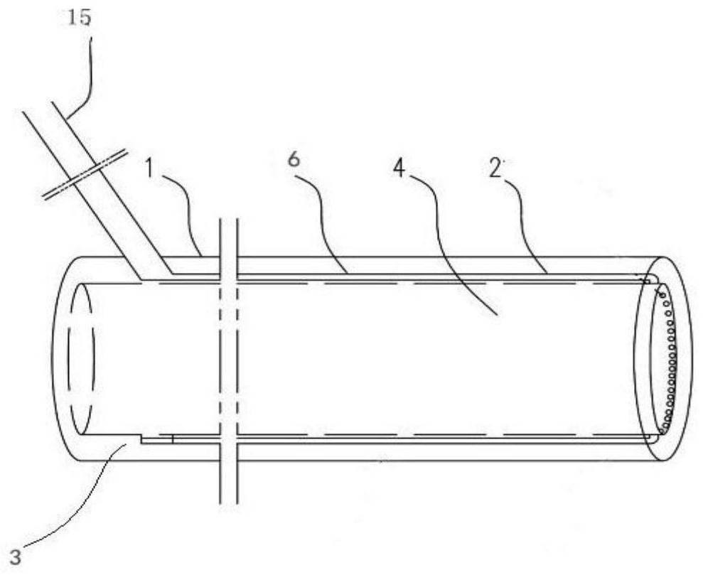
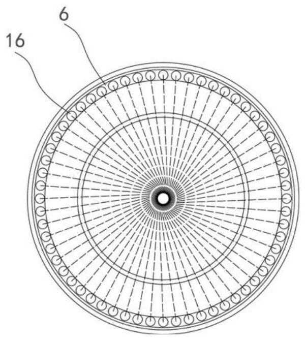
[0092] Such as Figure 1-15 Among them, a laser catheter includes a tube body 1, and the tube body 1 includes a head end 2, a tail end 3, a tube wall 4 and a tube cavity 5, and a plurality of ring-shaped continuous or discontinuous optical fibers are fixed in the tube wall 4 6. After the optical fiber 6 extends to a preset distance from the head end 2 in the tube wall 4, set the optical fiber bending 7, or the optical fiber side hole 17, or the ring optical fiber 61, or the optical reflection element, or combine the optical fiber bending 7, or The optical fiber side hole 17, or the annular optical fiber 61 and the optical reflective element are arranged to change the direction of the laser light, so that the laser light is directed to the lumen 5 after the longitudinal axis direction of the tube body 1 is changed to the radial direction of the cross section, and then the tissue entering the lumen 5 Perform ablation. Further, a plurality of optical fibers 6 are continuously or...

Embodiment 2

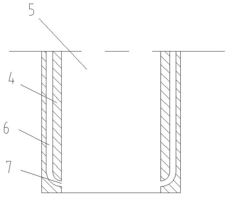
[0098] On the basis of Example 1, the preferred scheme is as image 3 Among them, the optical fiber 6 is extended through the tube wall to a preset distance from the head end 2, and an optical fiber bend 7 is set.

Embodiment 3

[0100] On the basis of Example 1, the preferred scheme is as Figure 4 and Figure 5 Among them, the optical fiber 6 is extended through the pipe wall to a preset distance from the head end 2, and a total reflection device 8 is provided. The total reflection device 8 is composed of an optically dense material and an optically sparse material to form a reflection interface, and the incident angle is set to be greater than or equal to the critical angle Elements make up. After the laser is transmitted to the head end through the optical fiber 6, it is totally reflected by the total reflection device 8, so that the laser is changed from the longitudinal axis direction of the tube body 1 to the radial direction of the cross section, and then shoots towards the lumen 5;

[0101] Further, the reflection interface of the total reflection device 8 is set to two or more, and the two or more interfaces are arranged at an angle in turn, so that the laser light is totally reflected twice...


PUM


Abstract

The invention relates to the field of medical equipment, and provides a laser catheter, comprising a tube body, the tube body includes a head end, a tail end, a tube wall and a lumen, a plurality of annular continuous or discontinuous optical fibers are arranged in the tube wall, and the laser passes through the optical fibers. After the tube wall is transmitted to a preset distance from the head end, the laser is directed to the lumen after changing the cross section of the longitudinal axis of the tube body radially to achieve ablation of the tissue entering the lumen. The laser catheter of the present invention provides a new laser ablation method, that is, the target ablation tissue is introduced into the lumen of the laser catheter of the present invention by using negative pressure or other methods, and then laser is used to ablate the tissue entering the lumen.

Description

technical field [0001] The invention relates to the field of medical instruments, in particular to a laser catheter. Background technique [0002] The current methods for tissue ablation or tissue removal through blood vessels or other internal lumens include: [0003] (1) Radiofrequency ablation uses the thermal effect of radiofrequency current to cause tissue necrosis, and the temperature is controlled at 37-55°C. This temperature can coagulate and necrosis the tissue, but it cannot be liquefied and removed. [0004] (2) Microwave ablation uses high-frequency electromagnetic waves to act on the tissue to rapidly generate heat and cause tissue necrosis. The temperature rises rapidly and easily damages the surrounding tissue. [0005] (3) Tissue rotary cutting uses a high-speed rotary atherectomy drill to remove tissue or grind and emulsify tissue into tiny particles to achieve the purpose of tissue ablation. [0006] (4) Tissue rotational atherectomy refers to the method ...

Claims


Application Information

Patent Timeline
Patent Type & Authority Patents(China)
IPC IPC(8): A61B18/24
CPCA61B18/24A61B2018/00404A61B2018/00589A61B2018/2205
Inventor 庞兴学
Owner DONGZHIMEN HOSPITAL OF BEIJING UNIV OF CHINESE MEDICINE
Why Eureka
Try Eureka