Intelligent positioning device for machining

A technology of processing intelligence and positioning device, which is applied in the field of mechanical processing, can solve the problems of complex surface structure of curved parts and difficult positioning of parts, and achieve the effect of increased cost and simple operation

Active Publication Date: 2020-04-21
XINXIANG UNIV
View PDF8 Cites 4 Cited by
  • Summary
  • Abstract
  • Description
  • Claims
  • Application Information

AI Technical Summary

Problems solved by technology

[0002] Mechanical processing refers to the process of changing the shape or performance of a workpiece through a mechanical device. According to the processing method, it can be divided into cutting processing and pressure processing; the mechanical production process refers to the entire process of making products from raw materials. In the production process Among them, the process of changing the shape, size, position and nature of the production object to make it a finished product or semi-finished product is called a process. It is the main part of the production process. Datum positioning must be used when positioning the workpiece. Positioning datum Divided into coarse reference positioning and fine reference positioning, but there is no positioning device specially for positioning thin-walled curved surface parts in the prior art. Due to the complex surface structure of curved surface parts, it is difficult to use conventional positioning parts to locate them

Method used


Image

  • Intelligent positioning device for machining
  • Intelligent positioning device for machining
  • Intelligent positioning device for machining

Examples


Embodiment 1

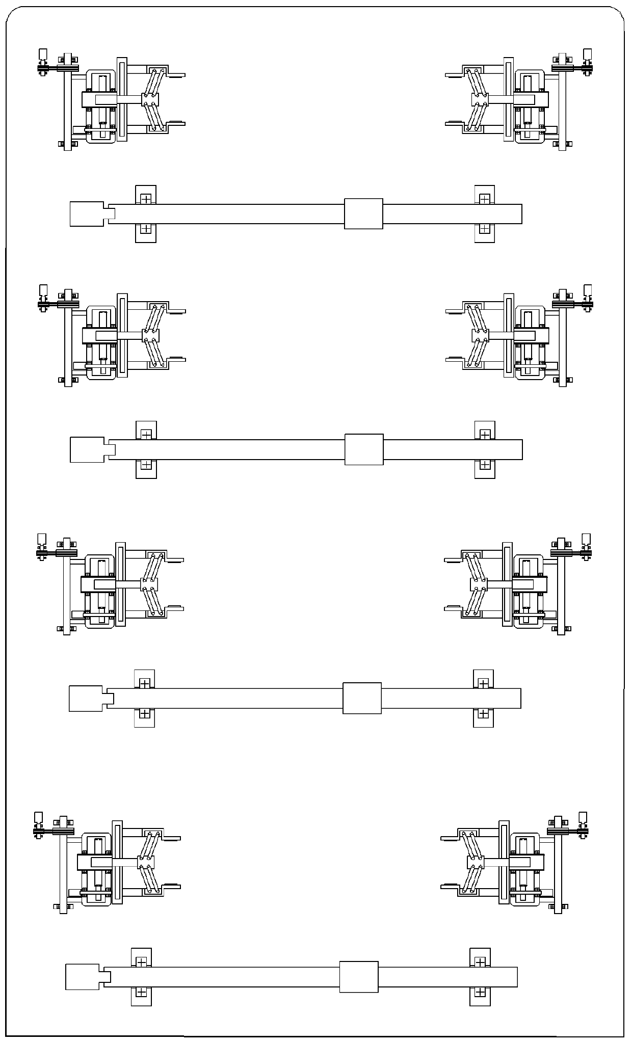
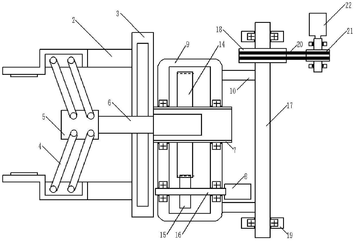
[0026] This embodiment provides a mechanical processing intelligent positioning device, which includes a positioning plate 1. The upper surface of the positioning plate 1 is provided with a plurality of clamping mechanisms for clamping thin-walled parts at different positions. The clamping mechanism includes two clamping mechanisms. Arm 2, the right ends of the two clamping arms 2 are slidably connected with the plate body 3 through a sliding assembly, the left ends of the two clamping arms 2 are fixedly connected with the block body 5 through the connecting rod 4, and the block body 5 is fixed on the first telescopic The telescopic end of the piece 6, the fixed end of the first telescopic piece 6 passes through the plate body 3 and is fixedly connected with the plate body 3; the side surface of the plate body 3 is fixed with a first rotating shaft 7, and the first rotating shaft 7 is connected to the first rotating shaft through a rotating mechanism. The output shaft of a moto...

Embodiment 2

[0031] This embodiment is based on Embodiment 1. The rotating mechanism includes a driven gear 14, the driven gear 14 is connected to the first rotating shaft 7 through a key, and both sides of the first rotating shaft 7 are connected to the housing 9 through bearings. The driving gear 14 meshes with the driving gear 15, and the driving gear 15 is connected with the second rotating shaft 16 through a key, and both sides of the second rotating shaft 16 are also connected with the housing 9 through bearings, and one end of the second rotating shaft 16 is connected with the first rotating shaft 16. The output shaft connection of the motor 8;

[0032] The rotary mechanism of the present application first starts the first motor 8 when in use, the first motor 8 drives the second rotating shaft 16 to rotate, the second rotating shaft 16 rotates to drive the driving gear 15 to rotate, the driving gear 15 rotates to drive the driven gear 14 to rotate, and the driven gear 14 rotates. Th...

Embodiment 3

[0034]This embodiment is based on Embodiment 1. The pitch angle adjustment mechanism includes a third rotating shaft 17, the side wall of the third rotating shaft 17 is fixedly connected to the ear plate 10, and one end of the third rotating shaft 17 is connected to the driven pulley 18 through a key. , both sides of the third rotating shaft 17 are connected with the first bearing seat 19 through bearings, the first bearing seat 19 is fixed on the upper surface of the positioning plate 1, the driven pulley 18 is connected with the driving pulley 21 through the timing belt 20, The central rotating shaft of driving pulley 21 is connected with second motor 22, and second motor 22 is the driver of pitch angle adjustment mechanism, and second motor 22 is connected with described microprocessor 11;

[0035] When the application needs to adjust the pitch angle, the control panel 29 sends a signal to the microprocessor 11, and the microprocessor 11 sends the signal to the second motor ...


PUM


Abstract

The invention provides an intelligent positioning device for machining. The intelligent positioning device comprises a positioning plate. A plurality of clamping mechanisms for clamping thin-walled parts at different positions are arranged on the upper surface of the positioning plate; the clamping mechanism comprises two clamping arms, the two clamping arms are connected with the plate body in asliding mode, the left ends of the two clamping arms are fixedly connected with a block body through a connecting rod, the block body is fixed to the telescopic end of a first telescopic piece, and the fixed end of the first telescopic piece penetrates through the plate body and is fixedly connected with the plate body; a first rotating shaft is fixed to the side face of the plate body and connected with the output shaft of a first motor through a rotating mechanism, the first rotating shaft is connected with a shell used for supporting the rotating mechanism through a bearing, and the left end and the right end of the shell are each fixedly provided with a lug plate connected with a pitch angle adjusting mechanism. A plurality of supporting mechanisms are also arranged on the upper surface of the positioning plate. According to the intelligent positioning device for machining, the intelligent positioning device is suitable for machining and positioning of thin-walled curved-surface parts and can clamp the parts and support the parts through the supporting mechanisms.

Description

technical field [0001] The invention belongs to the technical field of mechanical processing, and in particular relates to an intelligent positioning device for mechanical processing. Background technique [0002] Mechanical processing refers to the process of changing the shape or performance of a workpiece through a mechanical device. According to the processing method, it can be divided into cutting processing and pressure processing; the mechanical production process refers to the entire process of making products from raw materials. In the production process Among them, the process of changing the shape, size, position and nature of the production object to make it a finished product or semi-finished product is called a process. It is the main part of the production process. Datum positioning must be used when positioning the workpiece. Positioning datum It is divided into rough reference positioning and fine reference positioning, but there is no positioning device spe...

Claims


Application Information

Patent Timeline
IPC IPC(8): B23Q3/00
CPCB23Q3/00B23Q2703/10
Inventor 刘贵敏赖媛媛贾焕丽黄毅
Owner XINXIANG UNIV
Why Eureka
Try Eureka