Integrated molding machining system

A molding processing and turntable technology, applied in the field of integrated molding processing systems, can solve problems such as low work efficiency, poor stability, and short service life, and achieve the effects of saving manpower, good product quality, and strengthening integration and automation

Inactive Publication Date: 2020-04-21
昆山锐莱恩特精密机械有限公司
View PDF5 Cites 0 Cited by
  • Summary
  • Abstract
  • Description
  • Claims
  • Application Information

AI Technical Summary

Problems solved by technology

Most of the traditional driving mechanisms are semi-automatic or even traditional manual operation, and generally can only meet the processing of one station. In the current automation environment, the number of processing stations is huge and the production accuracy is getting higher and higher. The traditional drive There are many shortcomings in the working process of the mechanism, such as: low working efficiency, poor operation stability and short service life. Therefore, in order to solve the above problems, it is necessary to use an automatic driving mechanism

Method used


Image

  • Integrated molding machining system
  • Integrated molding machining system
  • Integrated molding machining system

Examples


Embodiment 1

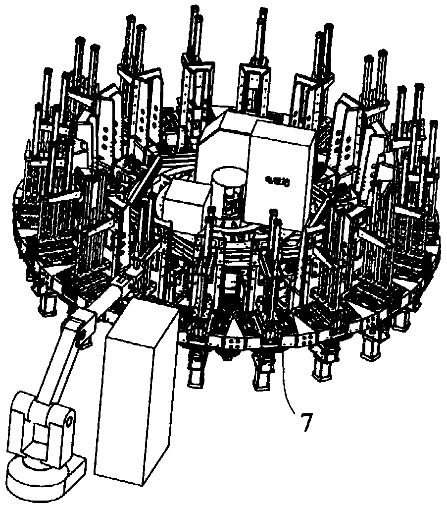
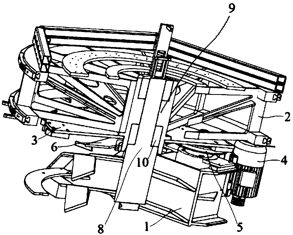
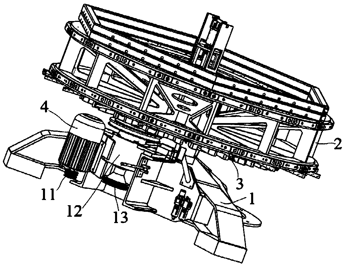
[0041] Embodiment 1: An integrated molding processing system, including a base 1, a turntable 2, a turntable 3, a motor 4, a drive turntable 5, a brake assembly 6 and several injection molding mechanisms 7, and the turntable 2 is rotatably mounted on the base 1, the turntable 3 is installed and connected with the turntable 2 to drive the turntable 2 to rotate, the motor 4 is installed on the base 1, the motor 4 is connected to the drive turntable 5, and the brake assembly 6 is installed on the base 1, used to brake the turntable 2, and the plurality of injection molding mechanisms 7 are installed on the turntable 2 at equal intervals in the circumferential direction;

[0042] The upper surface of the driving turntable 5 is provided with two circular protrusions 18, and the lower surface of the turntable 3 is provided with several pairs of clamping strips 17, and a strip for the insertion of the circular projections 18 is formed between each pair of clamping strips 17. Shaped g...

Embodiment 2

[0052] Embodiment 2: An integrated molding processing system, including a base 1, a turntable 2, a turntable 3, a motor 4, a drive turntable 5, a brake assembly 6 and several injection molding mechanisms 7, and the turntable 2 is rotatably mounted on the base 1, the turntable 3 is installed and connected with the turntable 2 to drive the turntable 2 to rotate, the motor 4 is installed on the base 1, the motor 4 is connected to the drive turntable 5, and the brake assembly 6 is installed on the base 1, used to brake the turntable 2, and the plurality of injection molding mechanisms 7 are installed on the turntable 2 at equal intervals in the circumferential direction;

[0053] The upper surface of the driving turntable 5 is provided with two circular protrusions 18, and the lower surface of the turntable 3 is provided with several pairs of clamping strips 17, and a strip for the insertion of the circular projections 18 is formed between each pair of clamping strips 17. Shaped g...


PUM


Abstract

The invention discloses an integrated molding machining system. The integrated molding machining system comprises a base, a rotating stand, a rotating disc, a motor, a driving rotating disc, a brakingassembly and a plurality of injection molding mechanisms, wherein the rotating stand is rotationally mounted on the base, the rotating disc is installed and connected on the rotating stand and used for driving the rotating stand to rotate, the motor is mounted on the base, a strip-type slot for round bulge blocks to be embedded is formed between each pair of clamping strips, the round bulge blocks rotate along with the rotating disc to sequentially enter or leave the strip-type slots between the clamping strips, a stand column is arranged on the base, one end of each clamping jaw is connectedwith a braking cylinder, one of the pair of the clamping jaws is connected with a piston rod of the braking cylinder, and the other jaw of the pair of the clamping jaws is connected with the end, away from the piston rod, of the braking cylinder. The integrated molding machining system drives the rotating disc by the motor, is ingenuous in structure, realizes frees switching among multiple stations, can realize continuous operation for multiple stations without manual intervention and improves the work efficiency.

Description

technical field [0001] The invention relates to an integrated molding processing system, which belongs to the technical field of automatic processing. Background technique [0002] With the rapid development of modern industry, most of the mechanical equipment presents the characteristics of automation, and the automatic driving mechanism emerges at the historic moment in this environment, and most of them are suitable for various automatic and semi-automatic equipment. Most of the traditional driving mechanisms are semi-automatic or even traditional manual operation, and generally can only meet the processing of one station. In the current automation environment, the number of processing stations is huge and the production accuracy is getting higher and higher. The traditional drive There are many shortcomings in the working process of the mechanism, such as: low working efficiency, poor running stability and short service life. Therefore, in order to solve the above proble...

Claims


Application Information

Patent Timeline
Patent Type & Authority Applications(China)
IPC IPC(8): B29C45/03B29C45/17B29C45/73B29C45/26
CPCB29C45/03B29C45/17B29C45/26B29C45/73
Inventor 黄彪韩飞谷东福
Owner 昆山锐莱恩特精密机械有限公司
Why Eureka
Try Eureka