
Combined sludge conditioning tank and continuous sludge conditioning process

A sludge conditioning and combined technology, applied in water/sludge/sewage treatment, dehydration/drying/thickened sludge treatment, water/sewage treatment, etc., can solve the problem of large volume, high cost and long conditioning time of the conditioning tank and other problems, to achieve the effect of short conditioning time, low cost and improved efficiency

Pending Publication Date: 2020-04-21
湖南隆泰资源再生利用技术有限公司
View PDF2 Cites 6 Cited by
  • Summary
  • Abstract
  • Description
  • Claims
  • Application Information

AI Technical Summary

Problems solved by technology

The conditioning time is still long, and the volume of the conditioning pool is large. At least 4 or more conditioning pools need to be built, and the cost is high

Method used


Image

  • Combined sludge conditioning tank and continuous sludge conditioning process
  • Combined sludge conditioning tank and continuous sludge conditioning process

Examples


Embodiment 1

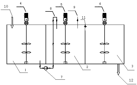
[0020] refer to figure 1 , the combined sludge conditioning tank in this embodiment includes a buffer tank 1, a sludge mixing tank 2 and a homogenization tank 3, and the buffer tank 1, the mud mixing tank 2 and the homogenization tank 3 adopt a common wall design; the buffer tank 1 The upper part of the buffer tank is provided with a sludge inlet 10, and the bottom of the buffer tank is provided with a sludge delivery pipeline 8 with a sludge delivery pump 7 to communicate with the upper part of the mud medicine mixing tank 2; the top of the mud medicine mixing tank 2 is provided with a belt The drug delivery pipeline 9 of the drug delivery pump, the upper part of the mud medicine mixing tank 2 and the upper part of the homogenization tank 3 are provided with passages, that is, the gap 11 on the common wall of the upper part of the mud medicine mixing tank 2 and the upper part of the homogenization tank 3 communicates with each other , the bottom of the homogenization tank 3 i...

Embodiment 2

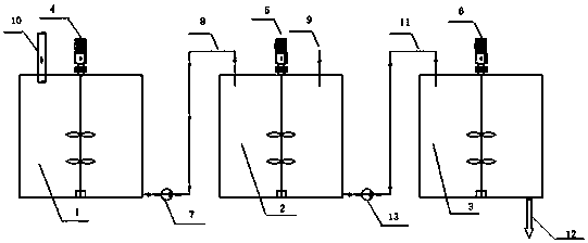
[0023] refer to figure 2 , the combined sludge conditioning tank in this embodiment includes a buffer tank 1, a sludge mixing tank 2 and a homogenization tank 3, and the buffer tank 1, the mud mixing tank 2, and the homogenization tank 3 are designed separately; the buffer tank 1 The upper part is provided with a sludge inlet 10, and the bottom of the buffer tank is provided with a sludge delivery pipeline 8 with a sludge delivery pump 7 to communicate with the upper part of the mud medicine mixing tank 2; the top of the mud medicine mixing tank 2 is provided with a The medicament delivery pipeline 9 of the delivery pump, the sludge delivery pipeline 11 with the sludge delivery pump 13 is provided in the lower part of the mud medicine mixing tank 2 to communicate with the upper part of the homogenization tank 3, and the lower part of the homogenization tank 3 is provided with There is a sludge outlet 12; the buffer tank 1, the mud medicine mixing tank 2 and the homogenization...


PUM


Abstract

The invention relates to a combined sludge conditioning tank and a continuous sludge conditioning process. The combined sludge conditioning tank comprises a buffer tank, a sludge and agent mixing tankand a homogenizing tank, wherein the upper portion of the buffer tank is provided with a sludge inlet, the lower portion of the buffer tank is provided with a sludge conveying pipeline communicated with the upper portion of the sludge and agent mixing tank, the sludge conveying pipeline is provided with a sludge conveying pump, an agent feeding port is formed in the top of the sludge and agent mixing tank, a channel for communicating the sludge and agent mixing tank and the homogenizing tank is arranged between the sludge and agent mixing tank and the homogenizing tank, a sludge outlet is formed in the lower portion of the homogenizing tank, and the buffer tank, the sludge and agent mixing tank and the homogenizing tank are respectively provided with an independent mixing stirrer. The invention further discloses a continuous sludge conditioning process using the combined sludge conditioning tank. With the application of the combined sludge conditioning tank to condition sludge, the agent and sludge mixing conditioning effect can be guaranteed to the maximum extent, the conditioning time is shortened, the sludge conditioning efficiency is improved, the number, the volume and the occupied area of the conditioning tank are reduced, and the investment cost is reduced.

Description

technical field [0001] The invention relates to a sludge treatment tank and a conditioning process, in particular to a combined sludge conditioning tank and a continuous sludge conditioning process. Background technique [0002] At present, the sludge conditioning process is divided into batch conditioning process and continuous conditioning process. At present the most common or intermittent conditioning process. The intermittent conditioning process has long sludge conditioning time and low conditioning efficiency. Usually, multiple conditioning tanks need to be built to meet the treatment requirements, which leads to a large area of ​​conditioning tanks, which in turn affects the investment and operating efficiency of the entire sludge dewatering system. [0003] CN 103896475A discloses a conditioning method for high-dry sludge dehydration. The method adopts an intermittent conditioning process, that is, sludge is first added to the conditioning tank, then ferric chlorid...

Claims


Application Information

Patent Timeline
Patent Type & Authority Applications(China)
IPC IPC(8): C02F11/14B01F13/10B01F7/18B01F15/00
CPCC02F11/14C02F2201/002B01F33/813B01F33/81B01F33/811B01F27/90B01F35/52
Inventor 熊刚周旋辉熊俊章磊徐滔明廖宁安
Owner 湖南隆泰资源再生利用技术有限公司
Learn More