Tubular braid manufacturing equipment

A technology for manufacturing equipment and braids, which is applied in the field of tubular braids manufacturing equipment, can solve the problems of unsatisfactory market demand, single types of braids, complex transmission structure, etc., and achieve simple structure, high-efficiency weaving requirements, and simple transmission structure. Effect

Pending Publication Date: 2020-04-21
NANTONG BECA MACHINERY TECH
View PDF0 Cites 2 Cited by
  • Summary
  • Abstract
  • Description
  • Claims
  • Application Information

AI Technical Summary

Problems solved by technology

[0004] When the circular warp and weft knitting machine of the prior art weaves large-diameter cylindrical braids, since the caliber of the braids becomes larger, the diameters and overall volumes of the various parts of the knitting machine will also increase accordingly, and are subject to the processing of existing parts. Due to the limitation of manufacturing equipment conditions, some key parts cannot be processed due to their large diameters. Therefore, the circular warp and weft knitting machines in the prior art can only produce cylindrical braids. The maximum weaving diameter can only reach 24 inches, which is difficult. It meets the above-mentioned shale gas exploitation and other occasions requiring large-diameter cylindrical braided fabrics, and the circular warp and weft knitting machines in the prior art use more gears in the transmission structure, which makes the transmission structure complex and prone to failure. There is also a lot of noise during work, and because the number of shuttles used in the knitting machine is not easy to change, the types of braided fabrics are relatively single, which cannot meet market demand

Method used


Image

  • Tubular braid manufacturing equipment
  • Tubular braid manufacturing equipment
  • Tubular braid manufacturing equipment

Examples


Embodiment Construction

[0027] In order to make the technical means and effects realized by the present invention easy to understand, the present invention will be described in detail below in conjunction with the embodiments and accompanying drawings.

[0028]

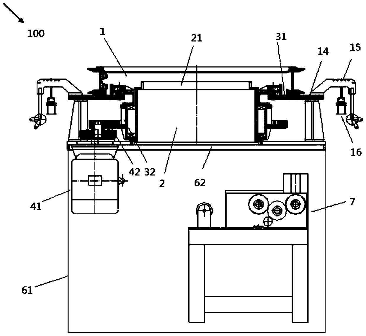
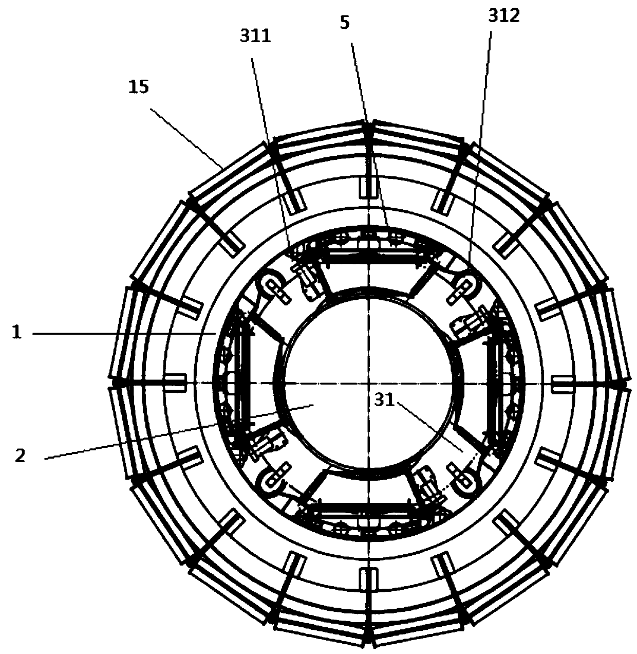
[0029] figure 1 is an overall structural diagram of the tubular braid manufacturing equipment of the embodiment of the present invention, figure 2 It is a top view of a cylindrical braid manufacturing equipment in an embodiment of the present invention.

[0030] Such as figure 1 and figure 2 As shown, the cylindrical braided fabric manufacturing equipment 100 of this embodiment is used to knit multi-ply yarns to obtain cylindrical braided fabrics, and has an annular frame body 1, a braided fabric guide cylinder 2, a rotary part 3, and a driving part 4. The shuttle 5 and the supporting part 6.

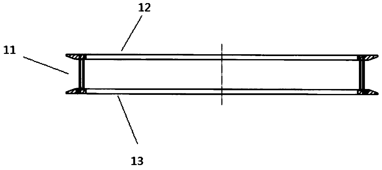
[0031] image 3 It is a sectional view of the annular frame body in the embodiment of the present invention, Figure 4 It is a top view of ...


PUM


Abstract

The invention provides tubular braid manufacturing equipment which is used for knitting multiple strands of yarns to obtain a tubular braid. The equipment comprises an annular frame body with a yarn guide ring, an upper frame portion extending along the edge of the upper side of the yarn guide ring and a lower frame portion extending along the edge of the lower side of the yarn guide ring, a braidguide barrel, a rotary part with a rotary disc arranged around the braid guide barrel and a matching part which is integrally formed together with the rotary disc and provided with a rotary gear, a driving part used for driving the rotary gear and driving the rotary disc to rotate, and a plurality of shuttles mounted in the annular frame body and used for loading and guiding yarns as wefts, wherein the upper frame portion is provided with an upper guide groove extending along the edge of the yarn guide ring, the lower frame portion is provided with a lower guide groove extending along the edge of the yarn guide ring, the rotary disc is provided with a shuttle pushing wheel and a yarn dividing plate wheel, the shuttles are arranged between the shuttle pushing wheel and a yarn dividing plate, are accommodated in the annular frame body and are embedded into the upper guide groove and the lower guide groove, and the number of the shuttles is changed to be two, four or six according to theknitting requirements.

Description

technical field [0001] The invention belongs to the field of knitting equipment, and in particular relates to a cylindrical knitting fabric manufacturing equipment. Background technique [0002] With the rapid development of urban construction, composite hoses are widely used in many fields such as remote water supply, flood fighting and emergency rescue, fire fighting and disaster relief, liquid oil and natural gas transportation. In order to improve the compressive strength of the hose, there is a layer of fiber-reinforced skeleton layer in the middle of the hose, and most of the fiber skeleton layer is woven by a circular warp and weft knitting machine. [0003] At present, the demand for composite hose applications is developing in the direction of diversification, multi-purpose, and large diameter, especially the market prospect of flat and coilable composite hoses required for shale gas exploitation is huge. [0004] When the circular warp and weft knitting machine of...

Claims


Application Information

Patent Timeline
IPC IPC(8): D03D37/00D03D51/02
CPCD03D37/00D03D51/02
Inventor 蔡卫丰蔡宝祥徐建辉樊柳唐蓉蓉
Owner NANTONG BECA MACHINERY TECH
Why Eureka
Try Eureka