Piston cylinder sleeve

A piston cylinder liner and piston technology, which is applied to cylinders, cylinder heads, engine components, etc., can solve the problems of uneven distribution of lubricating oil, reduced service life of pistons and piston liners, dry friction between pistons and cylinder liners, etc.

Active Publication Date: 2020-04-21
ANHUI UNIVERSITY OF TECHNOLOGY AND SCIENCE
View PDF6 Cites 0 Cited by
  • Summary
  • Abstract
  • Description
  • Claims
  • Application Information

AI Technical Summary

Problems solved by technology

[0003] The surface of the inner wall of the current piston and cylinder liner is smooth, and the lubricating oil cannot be evenly distributed between the piston and the cylinder liner. When the piston reciprocates in the cylinder liner, dry friction between the piston and the cylinder liner is prone to occur, and a large amount of heat is generated, which increases the The load on the piston and piston liner reduces the service life of the piston and piston liner

Method used


Image

  • Piston cylinder sleeve
  • Piston cylinder sleeve
  • Piston cylinder sleeve

Examples


Embodiment

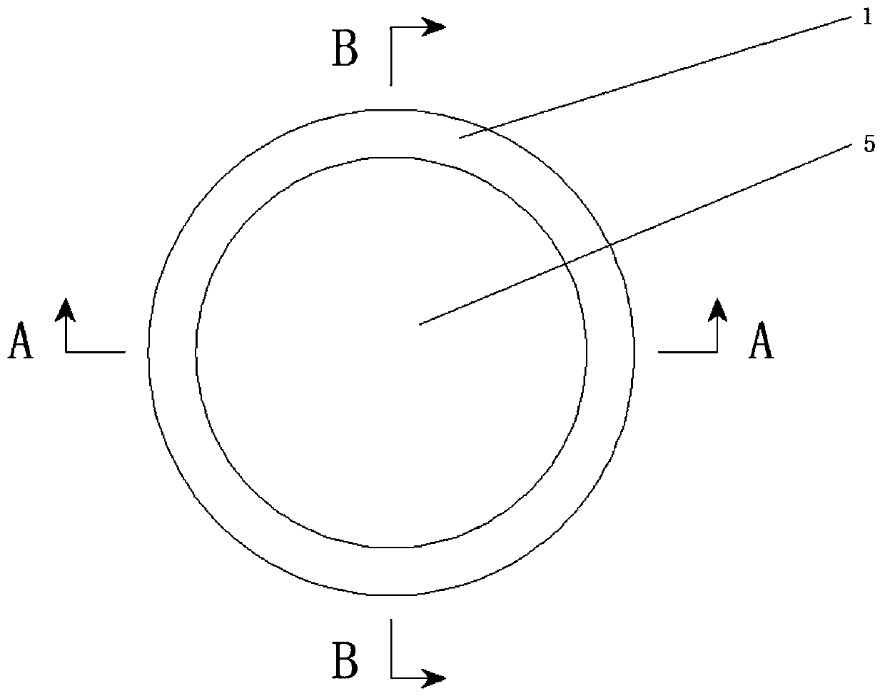
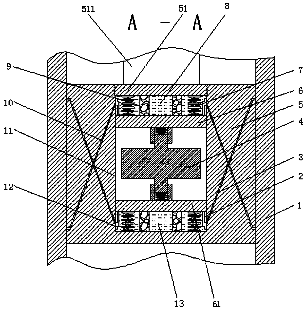
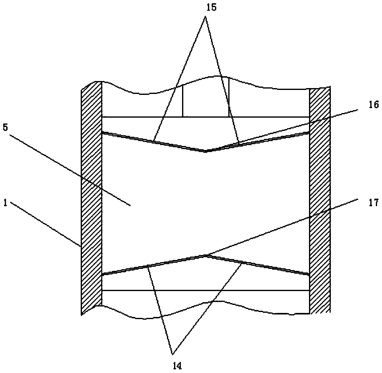
[0033] Such as Figure 1-10 A piston cylinder liner shown includes a cylinder liner 1, and also includes a piston 5 slidably arranged inside the cylinder liner 1. The outer walls of both sides of the top of the piston 5 are provided with positive eight-shaped oil delivery grooves 15, and the two The two ends of a positive figure-of-sight oil delivery groove 15 communicate with each other, the outer sidewalls of both sides of the bottom of the piston 5 are provided with an inverted figure-of-sight oil delivery groove 14, and the two ends of the two inverted figure-of-sight oil delivery grooves 14 Connected to each other, the middle position inside the piston 5 is provided with a sealing chamber 11, and the inner two ends of the sealing chamber 11 are respectively slidingly provided with a sealing piston plate 6 and a sealing piston plate 2 61, and a sealing piston plate 6 and a sealing piston plate 2 61 A piston chamber 1 8 and a piston chamber 2 13 are respectively arranged in...


PUM


Abstract

The invention discloses a piston cylinder sleeve. The piston cylinder sleeve comprises a cylinder sleeve body and further comprises a piston arranged in the cylinder sleeve body in a sliding mode. Oilconveying grooves shaped like a positive Chinese character eight are formed in the outer side walls of the two sides of the top of the piston, and the two ends of the two oil conveying grooves shapedlike the positive Chinese character eight communicate to each other. Oil conveying grooves shaped like an inverted Chinese character eight are formed in the outer side walls of the two sides of the bottom of the piston, and the two ends of the two oil conveying grooves shaped like the inverted Chinese character eight communicate to each other. According to the piston cylinder sleeve, when lubricating oil enters a first piston cavity and a second piston cavity through a first oil inlet channel and a second oil inlet channel, impurities among the piston cylinder sleeve can be brought into the first piston cavity and the second piston cavity, and sponge pads are arranged on the two sides in the first piston cavity and the two sides in the second piston cavity, so that the impurities enteringthe first piston cavity and the second piston cavity through the first oil inlet channel and the second oil inlet channel can be blocked by the two sponge pads and stay in the first piston cavity andthe second piston cavity, and meanwhile the impurities is prevented from being discharged again.

Description

technical field [0001] The invention relates to the technical field of piston and cylinder liners, in particular to a piston and cylinder liner. Background technique [0002] Cylinder liners are divided into two categories: dry cylinder liners and wet cylinder liners. The cylinder liner whose back side does not contact the cooling water is called a dry cylinder liner, and the cylinder liner whose back side is in contact with cooling water is a wet cylinder liner. The dry cylinder liner has a thinner thickness, simple structure and convenient processing. The wet cylinder liner is in direct contact with the cooling water, so it is beneficial to the cooling of the engine, and is conducive to the miniaturization and weight reduction of the engine. [0003] The surface of the inner wall of the current piston and cylinder liner is smooth, and the lubricating oil cannot be evenly distributed between the piston and the cylinder liner. When the piston reciprocates in the cylinder l...

Claims


Application Information

Patent Timeline
Patent Type & Authority Applications(China)
IPC IPC(8): F02F1/20F02F1/16
CPCF02F1/16F02F1/20
Inventor 苏永生钱立宏
Owner ANHUI UNIVERSITY OF TECHNOLOGY AND SCIENCE
Why Eureka
Try Eureka