Exhaust gas heating system of internal combustion engine

A technology for an internal combustion engine and an exhaust pipeline, which is applied in the field of the exhaust heating system of an internal combustion engine, can solve the problems of reducing output power, increasing fuel consumption, affecting engine ventilation, etc.

Inactive Publication Date: 2020-04-21
FAW JIEFANG AUTOMOTIVE CO
View PDF6 Cites 1 Cited by
  • Summary
  • Abstract
  • Description
  • Claims
  • Application Information

AI Technical Summary

Problems solved by technology

[0004] As the working time increases, more and more particles accumulate on the DPF, which will increase the exhaust back pressure and affect the ventilation of the engine, resulting in a decrease in output power and an increase in fuel consumption.

Method used


Image

  • Exhaust gas heating system of internal combustion engine

Examples


Embodiment Construction

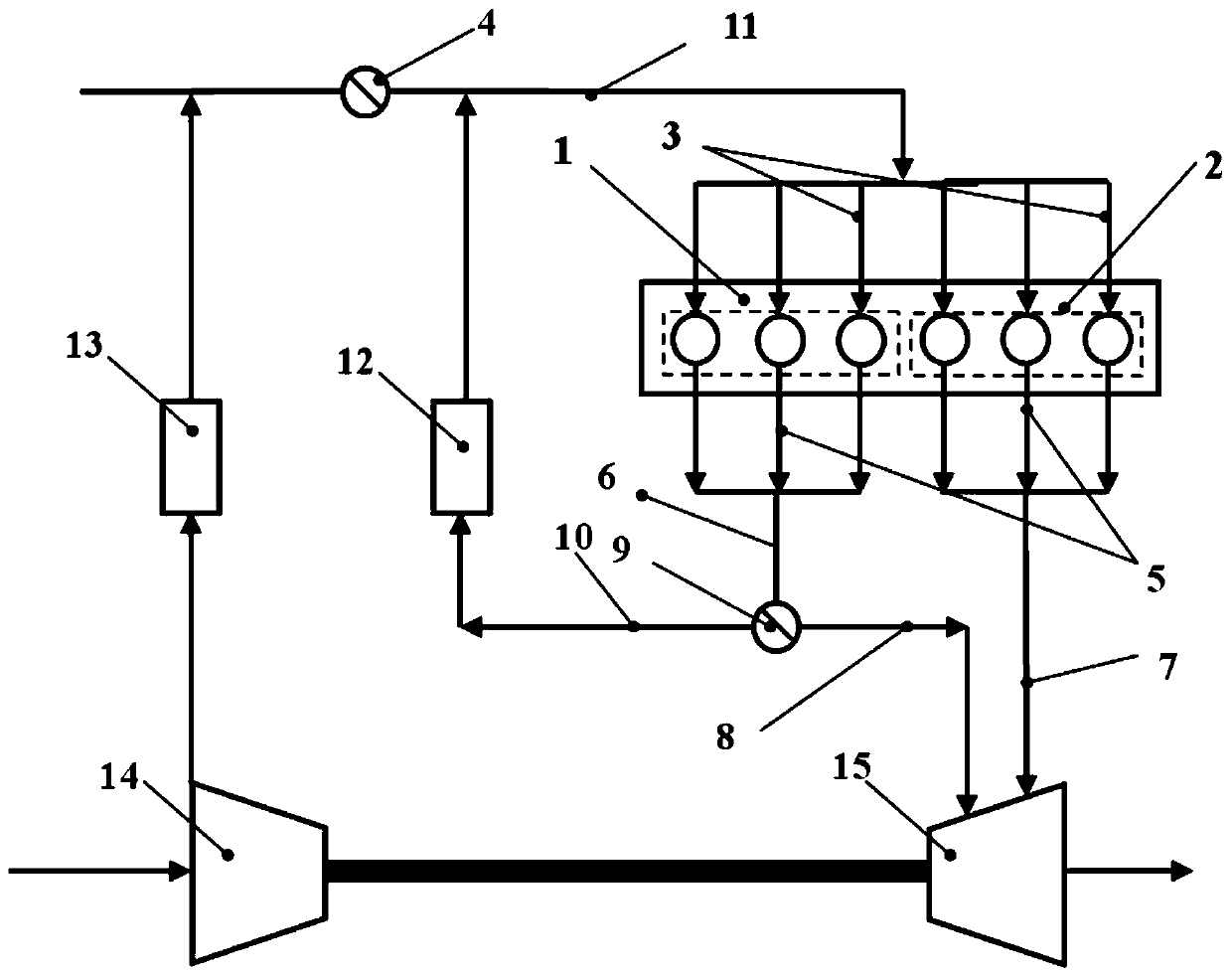
[0017] An internal combustion engine exhaust heating system of the present invention can refer to the attached figure 1 description of.

[0018] An exhaust heating system for an internal combustion engine, the engine is composed of at least two groups of cylinders, the two groups of cylinders are connected to the same intake manifold 11, and are connected through the intake passage 3; the two groups of cylinders are respectively connected to different exhaust pipelines, the first The group of cylinders 1 is connected to the first exhaust pipeline 6 through the exhaust manifold 5, and the second group of cylinders 2 is connected to the second exhaust pipeline 7 through the exhaust manifold 5; the intake manifold 11 is provided with an intake valve 4. It is used to control the intake air volume that can be adjusted and flows through the intake manifold 11; the second exhaust pipeline 7 is input into the turbocharger 15 turbine flow channel, and the gas flows through the turbine ...


PUM


Abstract

The invention discloses an exhaust gas heating system of an internal combustion engine, and belongs to the technical field of internal combustion engines. The exhaust gas heating system is characterized in that a control valve is additionally arranged on an exhaust gas pipeline added to a first set of air cylinders, when the engine is in cold starting and operates under medium and low loads, the exhaust gas temperature needs to be increased, only exhaust gas of a second set of air cylinders flows out and is input into an exhaust gas aftertreatment device, the first set of air cylinders achievecylinder closing, no exhaust gas flows out of the first set of air cylinders, meanwhile, an air inlet valve is adjusted, the gas inlet amount entering the two sets of air cylinders is reduced, fuel feeding to the first set of air cylinders is stopped, and the second set of air cylinders keep the output power of the engine unchanged by increasing the oil injection amount. The exhaust gas temperature can be increased so that the exhaust gas aftertreatment device can still reach the temperature required by efficient operation of the exhaust gas aftertreatment device, harmful substances containedin the exhaust gas can be fully converted or treated under the temperature condition, the exhaust gas flow is reduced, namely airflow speed is reduced, and the aftertreatment conversion efficiency isfavorably improved.

Description

technical field [0001] The invention belongs to the field of internal combustion engines, and in particular relates to an exhaust temperature raising system of an internal combustion engine. Background technique [0002] Exhaust aftertreatment devices are located in the exhaust pipe after the engine turbocharger to reduce or remove gases such as nitrogen oxides (NO or NO 2 , collectively referred to as NO x ) and particulate emissions), so as to meet the requirements of emission regulations. Now there are various types of exhaust after-treatment devices, such as Selective Catalytic Reduction (SCR) for NO x A treatment process, that is, under the action of the catalyst, in the post-treatment process, the dosing unit will accurately inject the amount of urea that matches the engine operating conditions into the exhaust gas according to the instructions given by the engine electronic control unit The ammonia and nitrogen oxides decomposed from urea undergo a catalytic reduct...

Claims


Application Information

Patent Timeline
Patent Type & Authority Applications(China)
IPC IPC(8): F02M26/05F02M26/13F02B37/00F02D21/08F02D17/02
CPCF02B37/00F02D17/02F02D21/08F02M26/05F02M26/13Y02T10/12
Inventor 郭立新钟博史艳彬董大陆兰权刘江唯
Owner FAW JIEFANG AUTOMOTIVE CO
Why Eureka
Try Eureka