
Flue gas treatment system suitable for heat recovery coke oven and application of flue gas treatment system

A flue gas treatment system and heat recovery technology, applied in waste heat treatment, gas treatment, furnaces, etc., can solve problems such as high production and construction costs, increased power consumption of fans, and waste of heat, so as to reduce production and construction costs and improve heat recovery The effect of low efficiency and smoke resistance

Pending Publication Date: 2020-04-21
HUATAI YONGCHUANG BEIJING TECH CO LTD
View PDF0 Cites 0 Cited by
  • Summary
  • Abstract
  • Description
  • Claims
  • Application Information

AI Technical Summary

Problems solved by technology

The temperature of the flue gas discharged from the heat recovery coke oven is above 1100°C, and the temperature of the SCR denitrification process is required to be around 300°C. Therefore, it is necessary to install a boiler before the denitrification device, and realize heat recovery while cooling the coke oven flue gas; and cooling The temperature after 300°C is still high, which causes two problems. One is to limit the heat recovery rate and cause heat waste. The other is to use a high temperature resistant fan in the system; in addition, the SCR denitration process needs to use a denitration catalyst. , in order to overcome the resistance of the catalytic layer, it is also required to increase the suction of the fan, which will increase the power consumption of the fan, so the requirements for the fan are very high, and the production and construction costs are high

Method used


Image

  • Flue gas treatment system suitable for heat recovery coke oven and application of flue gas treatment system
  • Flue gas treatment system suitable for heat recovery coke oven and application of flue gas treatment system

Examples


Embodiment Construction

[0017] The following will clearly and completely describe the technical solutions in the embodiments of the present invention with reference to the accompanying drawings in the embodiments of the present invention. Obviously, the described embodiments are only some, not all, embodiments of the present invention. Based on the embodiments of the present invention, all other embodiments obtained by persons of ordinary skill in the art without making creative efforts belong to the protection scope of the present invention.

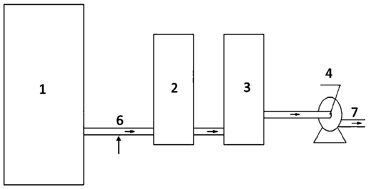
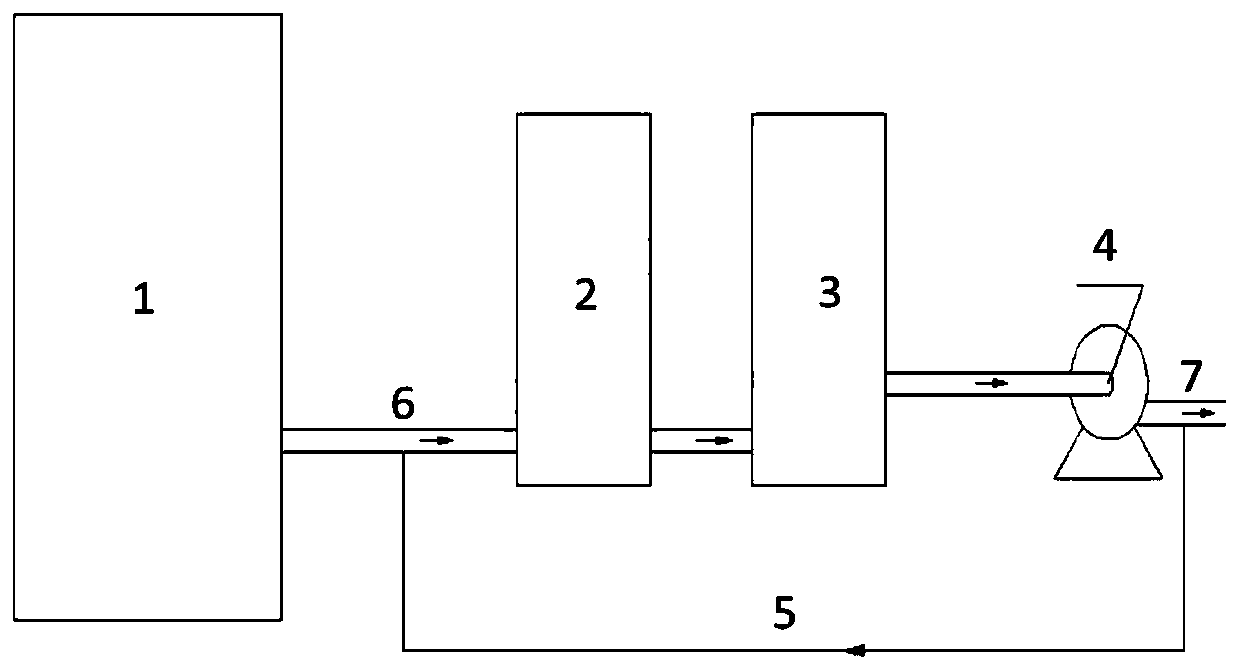
[0018] The first aspect of the present invention provides a flue gas treatment system suitable for heat recovery coke ovens, such as figure 1 As shown, it includes: along the flue gas discharge direction of coke oven 1, SNCR denitrification device 2, boiler 3 and fan 4 are sequentially connected through the flue gas discharge pipe; wherein the flue gas discharge pipe 6 at the front end of the SNCR denitrification device 2 is provided with a low temperature gas...


PUM


Abstract

The embodiment of the invention provides a flue gas treatment system suitable for a heat recovery coke oven and a method for treating coke oven flue gas by applying the system. The flue gas treatmentsystem comprises an SNCR denitration device, a boiler and a draught fan which are sequentially connected through a flue gas discharge pipeline in the flue gas discharge direction of the coke oven; anda low-temperature gas inlet is formed in the flue gas discharge pipeline in front of the SNCR denitration device. By adopting the flue gas treatment system and method provided by the embodiment of the invention, the denitration device can be directly connected to the coke oven, and high-temperature flue gas discharged by the coke oven is cooled by utilizing a small amount of low-temperature gas,so that denitration treatment can be directly carried out; the denitrated flue gas enters the boiler for heat recovery, heat can be fully recovered in the boiler due to the fact that a high-temperature reaction is not needed subsequently, and the heat recovery rate is increased; and the draught fan is arranged behind the boiler, and the smoke temperature is low, so that a high-temperature draughtfan is not needed, the smoke resistance in the system is small, the requirement for the draught fan is greatly reduced, and the production and construction cost is reduced.

Description

technical field [0001] The invention relates to the technical field of heat recovery coke oven flue gas treatment, in particular to a flue gas treatment system suitable for heat recovery coke oven and its application. Background technique [0002] Heat Recovery Coke oven flue gas has the characteristics of high temperature and high content of nitrogen oxides. Therefore, heat recovery and denitrification treatment are required before discharge. In the existing technology, coke oven flue gas adopts selective catalytic reduction flue gas denitrification technology (SCR Denitrification technology), that is, the use of ammonia to reduce nitrogen oxides in the flue gas at about 300 ° C by the action of a catalyst. The temperature of the flue gas discharged from the heat recovery coke oven is above 1100°C, and the temperature of the SCR denitrification process is required to be around 300°C. Therefore, it is necessary to install a boiler before the denitrification device to achieve...

Claims


Application Information

Patent Timeline
IPC IPC(8): F27D17/00B01D53/56B01D53/79
CPCB01D53/56B01D53/79B01D2258/0283F27D17/004F27D17/008F27D2017/006Y02P10/25
Inventor 马科伟徐列
Owner HUATAI YONGCHUANG BEIJING TECH CO LTD
Learn More