Speed reducer operation performance test platform

A technology of running performance and test platform, applied in the testing of mechanical components, testing of machine/structural components, mechanical equipment, etc., can solve the problems of inaccurate results, low safety, large number of people, etc., to improve the safety of use, The effect of reducing the outgoing noise

Active Publication Date: 2020-04-21
广东馥融传动科技有限公司
View PDF11 Cites 4 Cited by
  • Summary
  • Abstract
  • Description
  • Claims
  • Application Information

AI Technical Summary

Problems solved by technology

The current detection method is to test them one by one. The test requires a large number of people and a long time, and the results are not accurate enough, and the safety of the detection is low.

Method used


Image

  • Speed reducer operation performance test platform
  • Speed reducer operation performance test platform
  • Speed reducer operation performance test platform

Examples


Embodiment 1

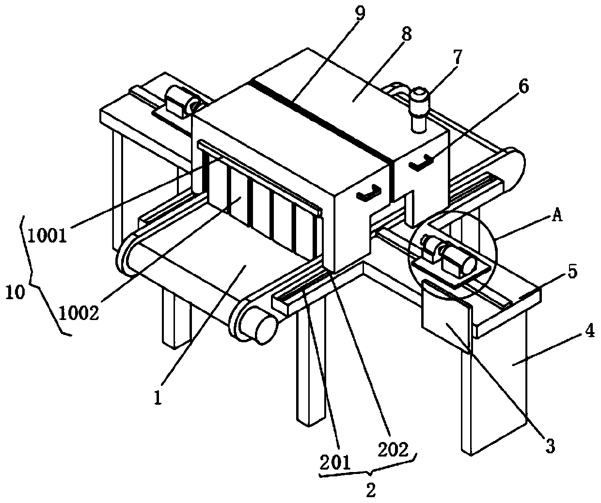
[0026]A reducer operating performance test platform, including a belt conveyor 1, a detection box 8, a protective mechanism 10, an infrared thermometer 12, a first testing mechanism 13, a first moving mechanism 14, a stepping motor 15 and a second testing mechanism 16. The front and rear surfaces of the belt conveyor 1 are provided with a T-shaped plate 5, and the bottom of the T-shaped plate 5 and the belt conveyor 1 are provided with feet 4. The reducer can be placed on the belt conveyor 1 for transportation, and the reducer can be moved to When the detection box 8 is inside, the belt conveyor 1 stops running. The detection box 8 is divided into two groups. 7, the inner cavity surface of the detection box 8 is provided with a noise detector 11, the detection box 8 is easy to move, which brings convenience to the test, the sound and light alarm 7 reminds the operator, and the noise detector 11 can detect noise in the reducer. The noise that sends out, protective mechanism 10 ...

Embodiment 2

[0031] The difference between this embodiment and embodiment 1 is:

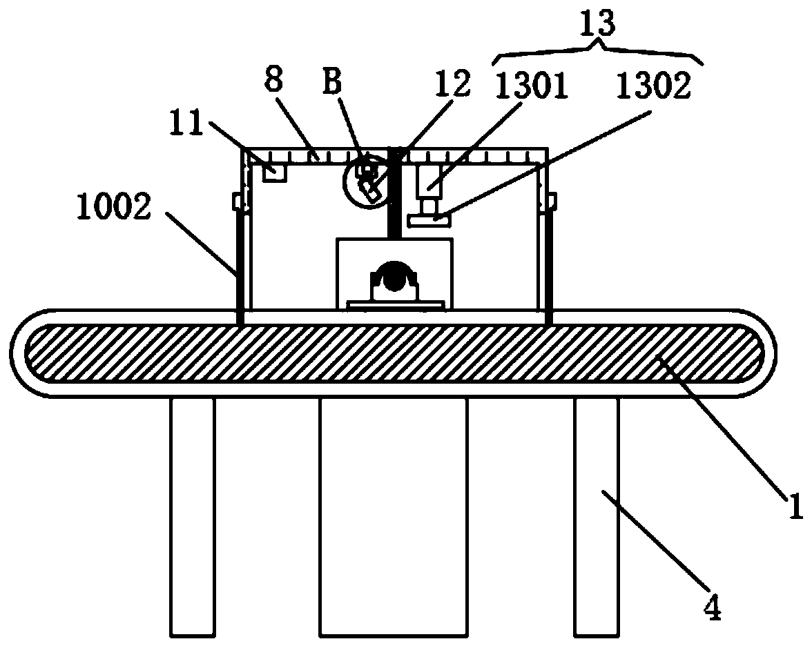
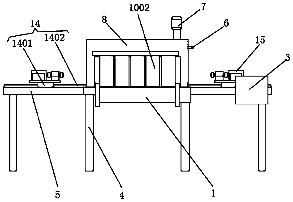
[0032] In this embodiment, the first test mechanism 13 includes an electric telescopic rod 1301 and a vibration recorder 1302, the vibration recorder 1302 is installed on the telescopic end of the electric telescopic rod 1301, and the electric telescopic rod 1301 is arranged on the inner cavity top surface of the detection box 8, The electric telescopic rod 1301 is electrically connected to the single-chip microcomputer 3, and the vibration recorder 1302 is electrically connected to the single-chip microcomputer 3. The first moving mechanism 14 includes a first guide rail 1401 and a first linear motor 1402, and the first linear motor 1402 is assembled on the first guide rail 1401. Above, the first guide rail 1401 is arranged on the T-shaped plate 5, the mounting plate 17 is arranged on the first linear motor 1402, and the first linear motor 1402 is electrically connected with the single-chip microcomputer 3, ...

Embodiment 3

[0035] The difference between this embodiment and embodiment 1 is:

[0036] In this embodiment, the second testing mechanism 16 includes a shaft coupling 1601 and a torque sensor 1602. There are two couplings 1601 installed on the ends of the input shaft and the output shaft of the torque sensor 1602 respectively. The torque sensor 1602 The shaft coupling 1601 at the end of the input shaft is connected to the output shaft of the stepper motor 15, the torque sensor 1602 is arranged on the mounting plate 17, the torque sensor 1602 is electrically connected to the single-chip microcomputer 3, and the second moving mechanism 19 includes a second straight line The motor 1901 and the second guide rail 1902, the second linear motor 1901 is assembled on the second guide rail 1902, the second guide rail 1902 is arranged on the inner cavity top surface of the detection box 8, the infrared thermometer 12 is assembled on the second linear motor 1901, The second linear motor 1901 is electr...


PUM


Abstract

The invention discloses a speed reducer operation performance test platform. The platform comprises a belt conveyor, detection boxes, protection mechanisms, an infrared thermometer, a first test mechanism, a first moving mechanism, a stepping motor and a second test mechanism. T-shaped plates are arranged on the front surface and the rear surface of the belt conveyor; supporting legs are arrangedat the bottoms of the T-shaped plates and the bottom of the belt conveyor, the two sets of detection boxes are symmetrically arranged and assembled on the T-shaped plate through sliding mechanisms, audible and visual alarms are arranged on the detection boxes, noise detectors are arranged on the inner cavity faces of the detection boxes, and the protection mechanisms are installed at inlets and outlets of the two sets of detection boxes. The speed reducer operation performance test platform can perform integrated detection, shorten the test time, reduce the number of users, improve the test efficiency, improve the accuracy of various test results and improve the safety during detection.

Description

technical field [0001] The invention relates to the technical field of reducer assembly, in particular to a reducer operating performance test platform. Background technique [0002] The reducer is the intermediate link in which the power unit drives the actuator. It converts high-speed low torque into low-speed high torque. It is used in conjunction with the engine. The reducer is a precision instrument, and its quality directly determines the operating quality and work efficiency of the power unit. Therefore, in After the reducer is assembled, it needs to be strictly tested. The current detection method is to test them one by one. The test requires a large number of people and a long time, and the results are not accurate enough, and the safety of the detection is low. Contents of the invention [0003] The technical problem to be solved by the present invention is to overcome the existing defects and provide a reducer operating performance testing platform, which can p...

Claims


Application Information

Patent Timeline
Patent Type & Authority Applications(China)
IPC IPC(8): G01M13/028G05B19/042G01J5/00F16P1/02G08B7/06
CPCG01M13/028G05B19/0425G01J5/00F16P1/02G08B7/06
Inventor 曾广西
Owner 广东馥融传动科技有限公司
Why Eureka
Try Eureka