System and method for driving semiconductor laser based on DCDC power supply module or chip

A technology for power modules and lasers, applied in semiconductor lasers, devices for controlling laser output parameters, lasers, etc., can solve the problems of high power consumption and difficult external heat dissipation design, achieve low power consumption, reduce overall power consumption, and reduce difficulty Effect

Inactive Publication Date: 2020-04-21
QXP TECH INC
View PDF4 Cites 6 Cited by
  • Summary
  • Abstract
  • Description
  • Claims
  • Application Information

AI Technical Summary

Problems solved by technology

[0003] The purpose of the present invention is to propose a method and system for driving a semiconductor laser based on a DCDC power module or a chip to solve the problems of high power consumption and difficult external heat dissipation design when the existing semiconductor laser driver chip drives the laser to emit light.

Method used


Image

  • System and method for driving semiconductor laser based on DCDC power supply module or chip
  • System and method for driving semiconductor laser based on DCDC power supply module or chip
  • System and method for driving semiconductor laser based on DCDC power supply module or chip

Examples


Embodiment 1

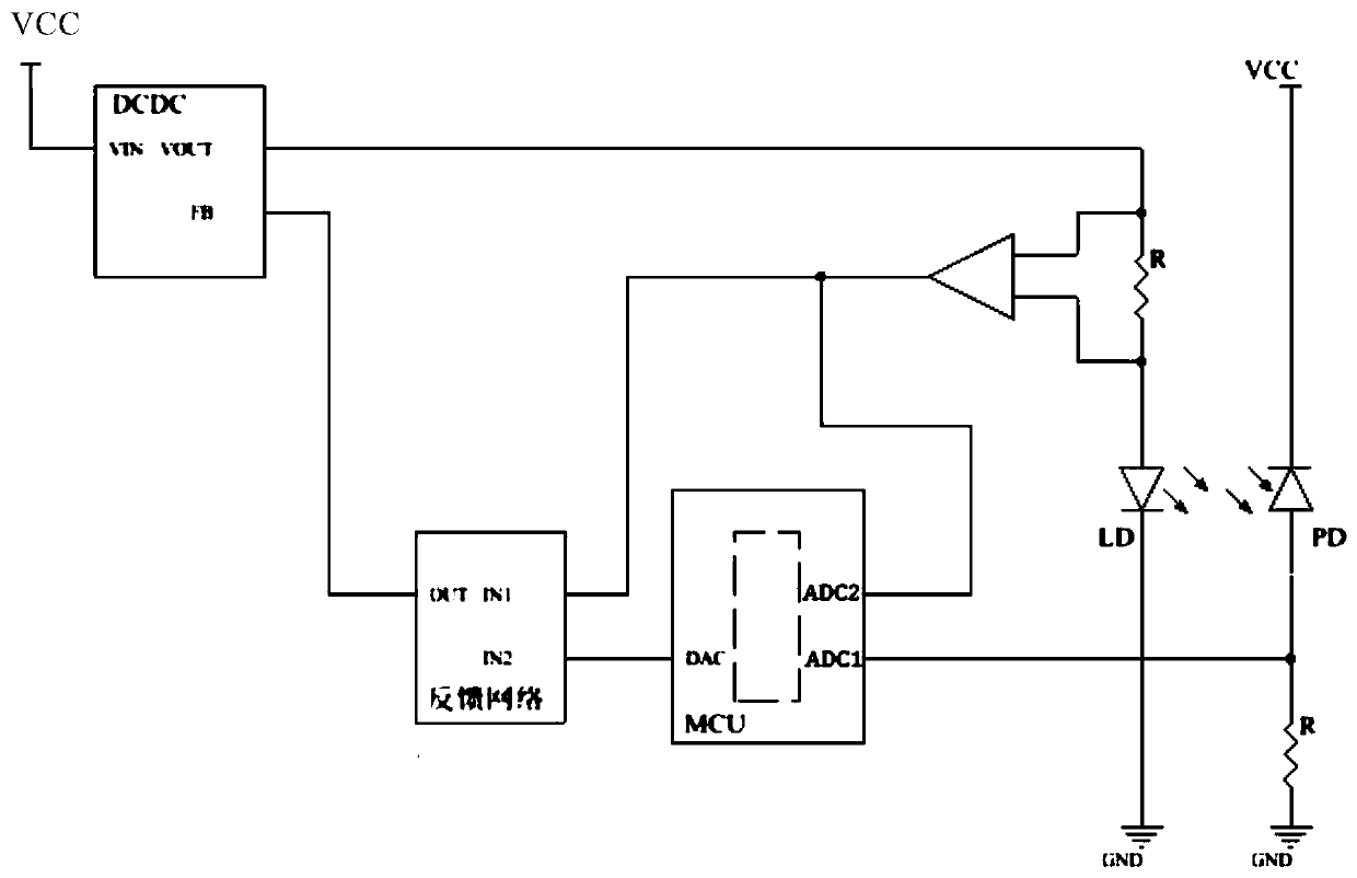
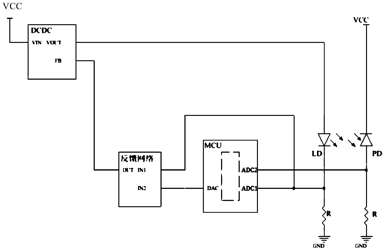
[0051] The driving part of this embodiment is composed of a DCDC power supply module or chip, and the sampling feedback and control part is composed of a current sampling circuit, a feedback network and an MCU control unit.

[0052] The DCDC power module or chip is used as the current drive source of the semiconductor laser to convert the power supply voltage of the module into the actual working voltage of the laser under specified working conditions. Of course, with the different requirements of the output optical power, this voltage will also change instead of a fixed value. .

[0053] The current sampling circuit includes two circuits, one of which is a driving current acquisition circuit, which collects the driving current of the semiconductor laser and converts it into a voltage signal; the other is a backlight current acquisition circuit, which collects the backlight current of the laser component and converts it into voltage signal.

[0054] As a control unit, the MCU...

Embodiment 2

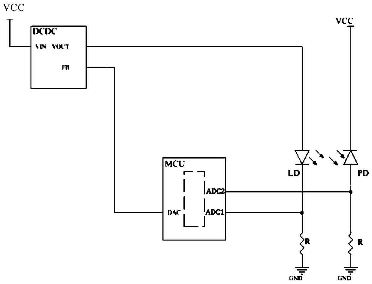
[0069] The driving part of this embodiment is composed of a DCDC power supply module or chip, and the sampling feedback and control part is composed of a current sampling circuit and an MCU control unit.

[0070] The DCDC power module or chip is used as the current drive source of the semiconductor laser to convert the power supply voltage of the module into the actual working voltage of the laser under specified working conditions. Of course, with the different requirements of the output optical power, this voltage will also change instead of a fixed value. .

[0071] The current sampling circuit includes two circuits, one of which is the driving current acquisition circuit, which collects the driving current of the semiconductor laser and converts it into a voltage signal; the other is the backlight current collection circuit, which collects the backlight current of the laser component and converts it into a voltage Signal.

[0072] As a control feedback unit, the MCU monit...


PUM


Abstract

The invention belongs to the field of optical communication modules, particularly relates to a system and a method for driving a semiconductor laser based on a DCDC power supply module or chip, and solves the problems of high power consumption, difficulty in external heat dissipation design and the like when an existing semiconductor laser driving chip drives the laser to emit light. In the system, the DCDC reduces the voltage and then supplies power to the semiconductor laser and then samples the current passing through the laser in real time; in addition, a MCU control unit is utilized to read real-time sampling, the MCU control unit is utilized to set the working current of the semiconductor laser, and finally sampling and setting are combined and fed back to the DCDC so that dynamic closed-loop constant-stable power driving of the semiconductor laser is realized. The main power consumption part of the semiconductor laser driving chip is externally arranged and voltage reduction iscarried out through the DCDC so that the semiconductor laser driving chip can be used for realizing higher-power output and longer-distance transmission of the semiconductor laser under the same powerconsumption.

Description

technical field [0001] The invention relates to a method for driving a semiconductor laser based on a DCDC power supply module or a chip, and belongs to the field of optical communication modules. Background technique [0002] In recent years, due to the rapid development of services such as high-definition video, data centers, smart homes, and virtual reality technology, people have higher and higher demands on the bandwidth, transmission rate, and transmission distance of communication networks. As the core device of optical communication network, high-speed optical communication transceiver module has always been the focus of people's research. The optical communication transceiver module mainly includes a semiconductor laser, a detector, a laser driver circuit, a detector limiting amplifier circuit, and an MCU control circuit. Among them, the laser drive circuit is generally integrated in the laser drive chip (including signal adjustment, pre-emphasis, equalization, las...

Claims


Application Information

Patent Timeline
Patent Type & Authority Applications(China)
IPC IPC(8): H01S5/042H01S5/06
CPCH01S5/042H01S5/0607
Inventor 范修宏骆弟伟赵越超王洋尚创波徐之光程东
Owner QXP TECH INC
Why Eureka
Try Eureka