Rotary wireless power transmission system

A wireless power transmission and rotary technology, applied in electrical components, circuit devices, etc., can solve the problems of different structure and size of turntables, unstable radar signals, increased labor costs, etc., to improve system efficiency and reliability, and high yield , The effect of saving system cost

Inactive Publication Date: 2020-04-21
成都天通电子科技有限公司 +1
View PDF3 Cites 6 Cited by
  • Summary
  • Abstract
  • Description
  • Claims
  • Application Information

AI Technical Summary

Problems solved by technology

At present, all radar equipment needs a turntable to rotate the radar antenna to smoothly detect and receive signals, and the equipment for transmitting and receiving signals on the turntable needs power supply, so there must be a motor brush in the turntable of the radar. The device—the slip ring, generally made of expensive metal materials and specially designed, it must work in a relatively clean environment and needs to be re

Method used


Image

  • Rotary wireless power transmission system
  • Rotary wireless power transmission system
  • Rotary wireless power transmission system

Examples


Example Embodiment

[0048] Embodiment 2 of Rotary Coupling Coil 4

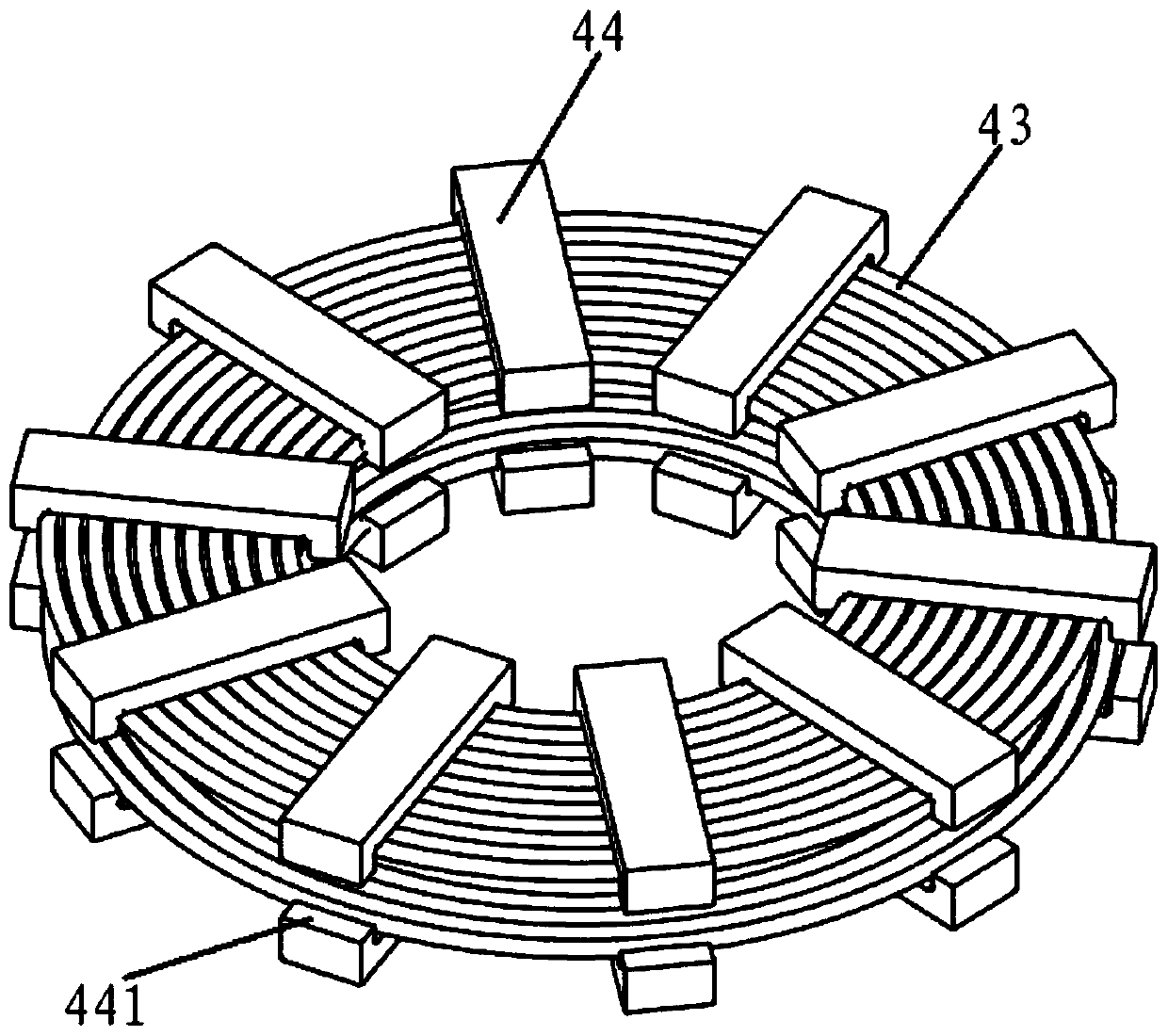
[0049] The primary side coupling device 41 and the secondary side coupling device 42 are both cylindrical in shape, and the axis lines of the two coincide with each other. device 42), the primary side coupling device 41 rotates relatively with the secondary side coupling device 42 through a bearing and does not contact. The primary side coupling device 41 and the secondary side coupling device 42 both include a coupling coil 43, a strip-shaped magnetic core 44, and an aluminum shielding layer 45. The coupling coil 43 is a cylindrical spiral coil, and the aluminum shielding layer 45 is a cylindrical shape. Aluminum tube (the upper and lower edges of the aluminum shielding layer 45 on the secondary side coupling device 42 are folded outwards, and the upper and lower edges of the aluminum shielding layer 45 on the primary side coupling device 41 are folded inwards), its function is to well surround On the outside of the coil, the i...


PUM


Abstract

The invention discloses a rotary wireless electric energy transmission system and relates to a load and a power frequency alternating current power source. The rotary wireless electric energy transmission system comprises a rectifying and filtering circuit, a primary side high-frequency inversion circuit, a primary side compensation circuit, a rotary coupling coil, a secondary side compensation circuit and a secondary side rectifying circuit which are connected in sequence; the input end of the rectifying and filtering circuit is connected with two ends of the power frequency alternating current power source; the output end of the secondary side rectifying circuit is connected with the input end of the load; the rotary coupling coil comprises a primary side coupling device and a secondaryside coupling device; the primary side coupling device and the secondary side coupling device rotate relatively through a bearing and do not make contact with each other. With the system of the invention adopted, contact abrasion between a contact collector rings is avoided, and cost is reduced. The rotary wireless electric energy transmission system has the advantages of stable signals, reliablework and long service life, and is not influenced by various environmental factors such as dust and dirt, thereby greatly reducing the cost of a wireless power transmission part.

Description

technical field [0001] The invention relates to the technical field of wireless power transmission, in particular to a rotary wireless power transmission system. Background technique [0002] Wireless power transmission, also known as wireless power transmission, non-contact power transmission, is to convert electric energy into other forms of relay energy (such as electromagnetic field energy, laser, microwave and mechanical waves, etc.) The receiving circuit converts the relay energy into electrical energy to realize wireless energy transmission. According to the different forms of relay energy in the energy transmission process, wireless energy transmission can be divided into: magnetic (field) coupling, electric (field) coupling, electromagnetic radiation (such as solar radiation), mechanical wave coupling (ultrasound). Among them, the magnetic coupling method is currently the most popular wireless energy transmission method, that is, the high-frequency power is loaded ...

Claims


Application Information

Patent Timeline
IPC IPC(8): H02J50/10H02J50/70
CPCH02J50/10H02J50/70
Inventor 张鸿许建平王孝强何激扬
Owner 成都天通电子科技有限公司
Why Eureka
Try Eureka