
Wear-resistant part with space latticed ceramic-metal composite layer and preparation method thereof

A technology of ceramic metal and space grid, which is applied in the field of wear-resistant composite materials, can solve the problems of block shedding, limited strength and wear resistance of the composite layer, and the reduction of the volume fraction of ceramic particles in the composite layer. Excellent impact resistance and wear resistance

Inactive Publication Date: 2020-04-24
CHONGQING LUOMAN NEW MATERIAL TECH CO LTD
View PDF9 Cites 3 Cited by
  • Summary
  • Abstract
  • Description
  • Claims
  • Application Information

AI Technical Summary

Problems solved by technology

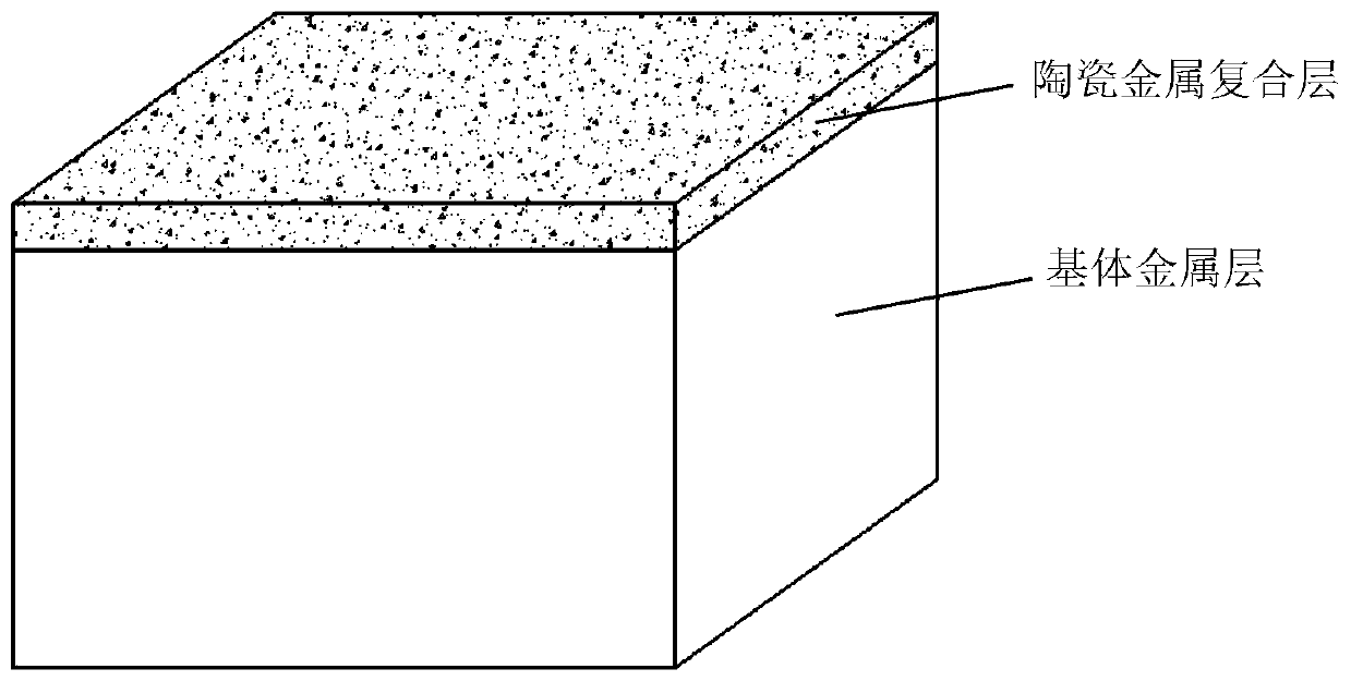
In the traditional full-layer ceramic-metal composite material, the ceramic particles are evenly dispersed in the entire composite layer. There are only small pore channels between the ceramic particles inside the composite layer, and the thickness of the metal liquid that can completely penetrate is very limited, generally not exceeding 10mm, resulting in the composite layer. The strength and wear resistance are extremely limited; the whole layer of ceramic-metal composite material layer is also easy to fall off in the form of blocks during wear
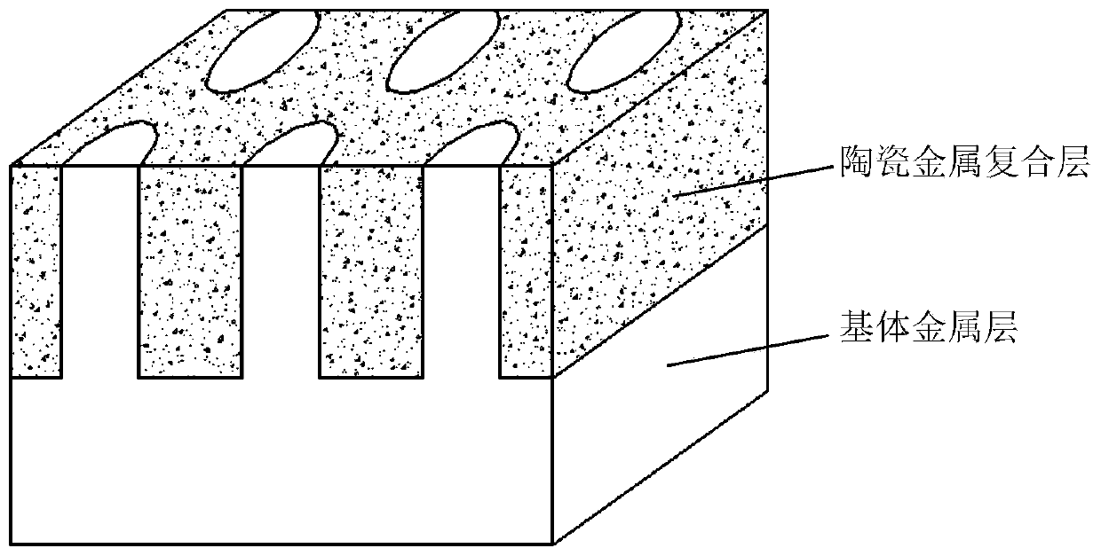
The second type of wear-resistant parts adopts honeycomb columnar locally reinforced composite materials in its working area. The wear-resistant parts of honeycomb columnar locally reinforced composite materials usually adopt a porous structure similar to honeycomb briquettes in the ceramic prefabricated body, such as figure 2 As shown; Although the wear-resistant parts of honeycomb columnar locally reinforced composite materials increase the penetration ability of molten metal, usually the casting penetration thickness can reach 60mm, but the volume fraction of ceramic particles in the composite layer decreases, which weakens the wear resistance of the composite material; During the manufacturing process, the ceramic-metal composite area of ​​the honeycomb column-shaped locally reinforced composite wear-resistant parts is easy to crack; in addition, the honeycomb column is a concentrated area of ​​large metal matrix. Difficult to provide effective support for the Multiple District

Method used


Image

  • Wear-resistant part with space latticed ceramic-metal composite layer and preparation method thereof
  • Wear-resistant part with space latticed ceramic-metal composite layer and preparation method thereof
  • Wear-resistant part with space latticed ceramic-metal composite layer and preparation method thereof

Examples


preparation example Construction

[0036] The preparation method of the wear-resistant part with the space grid shape ceramic metal composite layer of the present invention comprises the following steps:

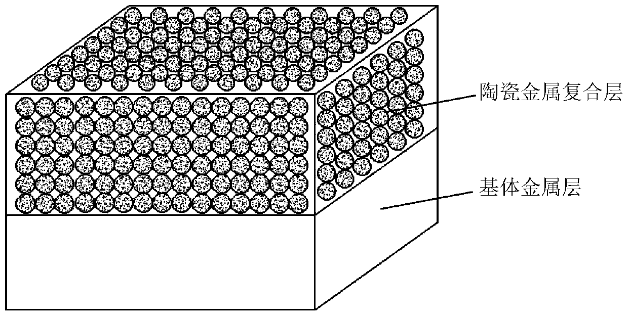
[0037] Step (1): using a binder to agglomerate the dispersed ceramic particles into a spherical ceramic preform, and the interior of the ceramic preform is formed by accumulation of ceramic particles to form interconnected pores;

[0038]Step (2): The spherical ceramic preform in step (1) is molded into a ceramic block by using a mesh metal outer frame or by using a binder and a ceramic block mold, then drying the ceramic block, and then drying the dried ceramic block The block is placed in the sand mold cavity of the wear-resistant part;

[0039] Step (3): Casting the matrix molten metal into the sand mold cavity, and obtaining a wear-resistant part with a space-grid-shaped ceramic-metal composite layer after forming.

[0040] The above-mentioned step (2) specifically includes the following steps: (2a) when...

Embodiment 1

[0045] The preparation of embodiment 1 wear-resistant hammer head

[0046] Step 1: Pretreatment of Ceramic Particles

[0047] The surface of the zirconium corundum ceramic particles with a particle size of 1.0-2.0mm and 2.0-4.0mm is subjected to nickel-plating treatment, and the mass ratio of the zirconium corundum ceramic particles with a particle size of 1.0-2.0mm and 2.0-4.0mm is 5:5 . The process of nickel plating includes the processes of surface treatment and plating.

[0048] Step 2: Preparation of ceramic preform

[0049] Mix the phenolic resin and the above-mentioned dispersed ceramic particles evenly, so that the phenolic resin evenly adheres to the surface of the ceramic particles, and then fill the mixed material in two molds with symmetrical hemispherical grooves, the balls of the hemispherical grooves The radius is 5 mm, and then the two molds are put together, and the mold is disassembled after the binder is solidified to obtain a spherical ceramic preform wi...

Embodiment 2

[0056] The preparation of embodiment 2 wear-resistant hammer head

[0057] Step 1: Pretreatment of Ceramic Particles

[0058] The surface of the zirconium corundum ceramic particles with a particle size of 1.0-2.0mm and 2.0-4.0mm is subjected to nickel-plating treatment, and the mass ratio of the zirconium corundum ceramic particles with a particle size of 1.0-2.0mm and 2.0-4.0mm is 5:5 . The process of nickel plating includes the processes of surface treatment and plating.

[0059] Step 2: Preparation of ceramic preform

[0060] Mix the phenolic resin and the above-mentioned dispersed ceramic particles evenly, so that the phenolic resin evenly adheres to the surface of the ceramic particles, and then fill the mixed material in two molds with symmetrical hemispherical grooves, the balls of the hemispherical grooves The radius is 5 mm, and then the two molds are put together, and the mold is disassembled after the binder is solidified to obtain a spherical ceramic preform wi...


PUM

PropertyMeasurementUnit
particle sizeaaaaaaaaaa
diameteraaaaaaaaaa
particle sizeaaaaaaaaaa

Abstract

The invention discloses a wear-resistant part with a space latticed ceramic-metal composite layer and a preparation method thereof. The preparation method comprises the following steps of firstly, forming ceramic particles into a spherical ceramic preform, stacking the spherical ceramic preform into a space latticed ceramic block, placing the ceramic block in a mold cavity, pouring molten metal into the mold cavity, and obtaining the wear-resistant part with the space latticed ceramic-metal composite layer after forming. The prepared wear-resistant part prepared by the preparation method is more excellent in strength and wear resistance and not prone to falling off, and the composite layer of the obtained wear-resistant part is large in thickness and longer in service life.

Description

technical field [0001] The invention relates to the technical field of wear-resistant composite materials, in particular to a wear-resistant part with a space grid ceramic-metal composite layer and a preparation method thereof. Background technique [0002] For wear-resistant parts used in the field of industrial crushing technology, wear is the most basic type of failure. At present, industries that widely use wear-resistant parts include metallurgy, mining, thermal power, machinery, cement, coal mines, etc. In order to improve the strength and wear resistance of wear-resistant parts, a layer of stronger wear-resistant materials, such as ceramic-metal composite materials, is usually compounded on the working wear part of the wear-resistant parts. [0003] As a new type of wear-resistant composite material, ceramic-metal composite materials have shown excellent performance in modern industrial production applications, and are gradually replacing traditional metal wear-resist...

Claims


Application Information

Patent Timeline
Patent Type & Authority Applications(China)
IPC IPC(8): B22D23/04C22C38/02C22C38/38C22C37/08C04B35/10C04B35/56C04B35/622
CPCB22D23/04C04B35/10C04B35/5611C04B35/622C22C37/08C22C38/002C22C38/02C22C38/38
Inventor 温放放侯占东黄东风牟元全
Owner CHONGQING LUOMAN NEW MATERIAL TECH CO LTD
Learn More