Automatic water-separating and dust-settling device for blast furnace gas

A blast furnace gas and dust reduction device technology, which is applied in the direction of gas dust removal, combustible gas purification, combustible gas purification/transformation, etc., can solve the problems of potential safety hazards, easy flameout, low calorific value, etc., to prolong the service life, the device structure is simple, Effect of improving gas quality

Pending Publication Date: 2020-04-24
临沂玫德庚辰金属材料有限公司
View PDF0 Cites 0 Cited by
  • Summary
  • Abstract
  • Description
  • Claims
  • Application Information

AI Technical Summary

Problems solved by technology

Due to the high water content and low calorific value of blast furnace gas, it is difficult to ignite and it is easy to extinguish when the working conditions fluctuate. The mechanical water of blast furnace gas will corrode the burner or furnace refractory lining, which will bring great safety hazards or shorten the life of combustion equipment. Blast furnace gas contains a lot of dust. After using blast furnace gas for a long time, the dust in the gas will also deposit in the gas channel, which will increase the resistance and affect the normal adjustment of heating. Therefore, cleaning measures need to be taken

Method used


Image

  • Automatic water-separating and dust-settling device for blast furnace gas

Examples


Embodiment 1

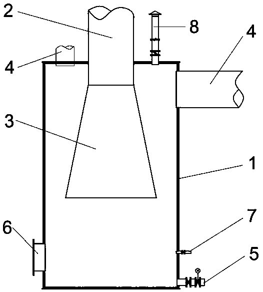
[0022] Using the present invention, nitrogen or steam is used to purge the interior of the equipment through the nitrogen or steam purge inlet 7, and the air in the pipe is discharged by the release pipe, and the blast furnace gas is transported through the gas inlet 2 into the trumpet tube 3 provided in the shell 1, and the blast furnace gas After entering the trumpet tube 3, it will decelerate and diffuse immediately, the kinetic energy will decrease, the dew point will drop rapidly, and a large amount of mechanical water will be precipitated. The mechanical water will fall to the lower part of the shell 1 by gravity. At the bottom of the cylinder, the gas passes through the gas outlet 4 above the cylinder, and is transported to other units through the gas pipeline as fuel, and the solenoid valve of the drainage and sewage valve group 5 is opened to discharge the water and dust precipitated at the bottom of the cylinder.

Embodiment 2

[0024] When maintaining and overhauling the equipment, use nitrogen or steam to purge the inlet 7 to purge the inside of the equipment, use the release pipe to discharge the gas in the pipe, prevent the formation of explosive mixed gas in the pipe, and open the manhole 6, Equipment personnel perform maintenance and overhaul.

[0025] In the present invention, the blast furnace gas containing dust and moisture enters the horn tube 3 from the gas inlet 2 through the horn tube 3, and immediately decelerates and diffuses, the kinetic energy decreases, the dew point drops rapidly, and a large amount of mechanical water is precipitated, and the mechanical water falls to the lower part of the cylinder body by gravity. At the same time as the moisture is precipitated, the dust in the gas and the mechanical water fall to the bottom of the cylinder under the action of gravity, and then are discharged from the drainage and sewage valve group 5. According to the actual measurement during t...


PUM

PropertyMeasurementUnit
diameteraaaaaaaaaa

Abstract

The invention discloses an automatic water separating and dust settling device for blast furnace gas. The device comprises a shell, a coal gas inlet, a horn pipe, a coal gas outlet and a drainage andblowdown valve group, the coal gas inlet is formed in the upper end of the shell and penetrates through the shell; the diameter of the upper end surface of the horn pipe is equal to that of the gas inlet; the upper end surface of the horn tube is smaller than the lower end surface; the horn tube is arranged in the shell; the upper end surface of the horn pipe is connected with the gas inlet; the coal gas inlet and the horn pipe are communicated and are positioned on the same axis; according to the water separation and dust falling device for the blast furnace gas, water separation and dust falling can be conducted on the blast furnace gas, the gas quality is improved, the combustion stability is improved, the structure is simple, and the effect is stable.

Description

technical field [0001] The invention relates to the technical field of tail gas treatment, in particular to an automatic water analysis and dust reduction device for blast furnace gas. Background technique [0002] Blast furnace gas is a by-product of blast furnace production in the ironmaking industry. It generally contains about 5mg / m3 of dust and 7g / m3 to 30g / m3 of moisture (the moisture content is even higher under special production conditions). It is generally used in other production processes or gas in the iron and steel industry. Fuel for power generation. Due to the high water content and low calorific value of blast furnace gas, it is difficult to ignite and it is easy to extinguish when the working conditions fluctuate. The mechanical water of blast furnace gas will corrode the burner or furnace refractory lining, which will bring great safety hazards or shorten the life of combustion equipment. Blast furnace gas contains a lot of dust. After long-term use of bl...

Claims


Application Information

Patent Timeline
Patent Type & Authority Applications(China)
IPC IPC(8): C10K1/02C10K1/00
CPCC10K1/00C10K1/02
Inventor 汪龙奎邱溆峰展新宇王宁舒磊宋传君崔士选
Owner 临沂玫德庚辰金属材料有限公司
Why Eureka
Try Eureka