
Engine piston cooling electromagnetic valve structure

A technology of piston cooling and solenoid valves, which is applied in the direction of engine cooling, engine components, machines/engines, etc., and can solve problems such as insufficient engine combustion and deterioration of emissions

Active Publication Date: 2020-04-24
JAPHL POWERTRAIN SYST
View PDF5 Cites 2 Cited by
  • Summary
  • Abstract
  • Description
  • Claims
  • Application Information

AI Technical Summary

Problems solved by technology

[0003] The technical problem to be solved by the present invention is to provide a simple structure that can control the solenoid valve through the electric signal (PWM signal) sent by the ECU, so that the flow can be adjusted according to the different signals sent by the ECU according to the engine working conditions, so that The fuel injection time and fuel injection volume during cooling are precisely matched with the engine operating conditions to improve the cooling effect, thereby precisely controlling the temperature required by the engine pistons, avoiding excessive cooling, and solving problems such as insufficient combustion of the engine and deterioration of emissions. Engine piston cooling solenoid valve structure

Method used


Image

  • Engine piston cooling electromagnetic valve structure

Examples


Embodiment Construction

[0020] Below with reference to the accompanying drawings, through the description of the embodiments, the specific embodiments of the present invention, such as the shape, structure, mutual position and connection relationship between the various parts, the role and working principle of the various parts, etc., will be further described. Detailed instructions:

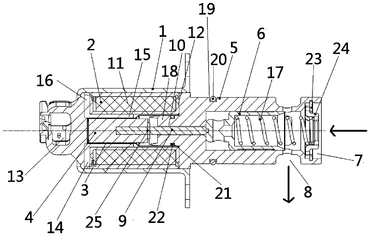
[0021] as attached figure 1 As shown, the present invention is an engine piston cooling solenoid valve structure, and the engine piston cooling solenoid valve structure includes a housing 1, a solenoid assembly 2, the solenoid assembly 2 is connected with the ECU, and the solenoid assembly 2 are installed in the housing 1, the magnetic core body 4 is movably installed in the solenoid assembly 2, and further includes a guide sleeve 3, and the guide sleeve 3 is installed in the solenoid assembly 2, and the solenoid assembly 2 are installed in the housing 1, the magnetic core body 4 is movably installed in the guide slee...


PUM


Abstract

The invention provides an engine piston cooling electromagnetic valve structure applied to the technical field of automobile engine parts. The engine piston cooling electromagnetic valve structure ischaracterized in that one end of a valve sleeve (5) is connected to a shell (1), a valve core (6) is movably arranged in the valve sleeve (5), the end face of the other end of the valve sleeve (5) isprovided with an oil inlet (7), the side face of the end, close to the oil inlet (7), of the valve sleeve (5) is provided with an oil outlet (8), a magnetic core shaft (9) is arranged on a magnetic core body (4), the magnetic core shaft (9) penetrates through a through hole (10) in the valve sleeve (5) to be connected with one end of the valve core (6), the valve sleeve (5) is provided with a front yoke sleeve (18) which forms an integrated structure with the valve sleeve (5), and the front yoke sleeve (18) extends from the other side of a coil (11) to the interior of the coil (11). Accordingto the engine piston cooling electromagnetic valve structure, according to engine working condition, different signals can be sent out through an ECU to adjust flow so that the oil injection time, theoil injection quantity and the engine working condition during cooling can be accurately matched.

Description

technical field [0001] The invention belongs to the technical field of automobile engine components, and more specifically relates to a structure of an engine piston cooling solenoid valve. Background technique [0002] With the application of technologies such as supercharging and high compression ratio on the engine, the combustion temperature of the engine is getting higher and higher, and the ambient temperature of the engine piston is also getting higher and higher. In order to solve the problem of cylinder scuffing caused by the high temperature of the piston position in the engine combustion chamber, and to improve the service life of the engine piston and cylinder, reduce the wear of the piston and cylinder, and improve fuel economy, piston cooling is used on the engine system. After the piston cooling system is used in the car, it can reduce the wear of the piston, prolong the life of the piston, and ensure the smooth operation of the engine. The control part of t...

Claims


Application Information

Patent Timeline
Patent Type & Authority Applications(China)
IPC IPC(8): F16K31/06F01P3/08
CPCF16K31/0644F16K31/0675F01P3/08
Inventor 李兵李后良姜倩丁万龙王友安方舫
Owner JAPHL POWERTRAIN SYST
Learn More