Combined prefabricated shear wall mold assembly and using method thereof

A prefabricated shear force and combined technology, applied in the direction of molds, manufacturing tools, unloading devices, etc., can solve the problems of high overall comprehensive cost, complex mold structure, difficult quality assurance, etc. Low, the effect of improving production efficiency

Inactive Publication Date: 2020-04-28
ZHONGTIAN CONSTR GROUP +1
View PDF3 Cites 3 Cited by
  • Summary
  • Abstract
  • Description
  • Claims
  • Application Information

AI Technical Summary

Problems solved by technology

However, the structure of the mold is relatively complicated, and the assembly of the mold is cumbersome. The assembly of the mold, the application of the release agent, and the binding of the steel bars need to be interspersed. The efficiency is low, the quality is not easy to guarantee, and the overall comprehensive cost is high.

Method used


Image

  • Combined prefabricated shear wall mold assembly and using method thereof
  • Combined prefabricated shear wall mold assembly and using method thereof
  • Combined prefabricated shear wall mold assembly and using method thereof

Examples


Embodiment 2

[0062] Embodiment two, such as Figure 10 Shown:

[0063] A method applicable to the above combined prefabricated shear wall mold assembly, the method includes the following steps:

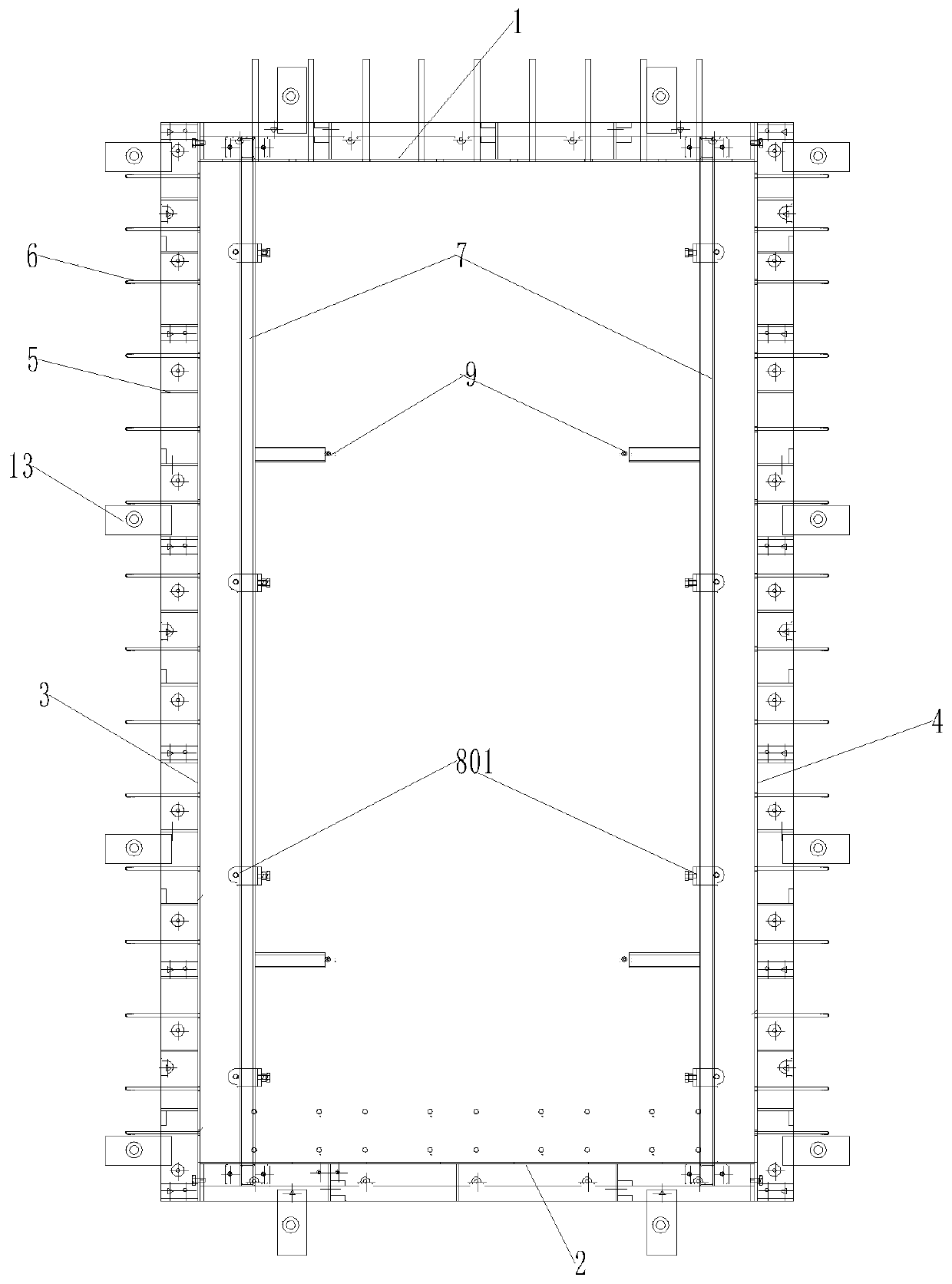
[0064] Step S01, processing the above-mentioned mold according to the shape, size and reinforcement arrangement of the prefabricated component to be formed;

[0065] Step S02, fixing the lower side molds of the left mold 3 and the right mold 4, the upper mold 1, and the lower mold 2 on the mold table with a fixed magnetic box 13, and each part of the mold is fixedly connected with bolts;

[0066] Step S03 Apply the adjusted mold release agent or exposed aggregate retarder (when there is a requirement for exposed coarse aggregate rough surface) evenly on the concrete contact surface of the mold to avoid missing coating and uneven

[0067] Step S04, according to the design drawing of the prefabricated shear wall, install stirrups and vertically stressed steel bars in the assembled mold, and after ...


PUM


Abstract

The invention belongs to the technical field of improvement of building prefabricated components, and discloses a combined prefabricated shear wall mold assembly and a using method thereof. The mold assembly comprises a pair of end molds and a pair of side molds, wherein the side molds and the end molds are alternately connected and fixed to form a prefabricated shear wall frame, each side mold comprises an upper pressing plate and a lower side mold, and the upper pressing plate is buckled and fixed on the lower side die. According to the technical scheme, the mold assembly has the advantagesof simplicity, convenience and rapidness in operation, good component forming quality and low mold manufacturing cost, the process is simplified, and the production efficiency is improved.

Description

technical field [0001] The invention belongs to the field of assembled prefabricated components, and in particular relates to a combined prefabricated shear wall mold assembly and its application method. Background technique [0002] Prefabricated shear wall components usually have steel bars protruding from the left side of the wall, the right side of the wall and the top of the wall. For the steel bars protruding from the left and right sides of the wall, there are currently two methods for the mold. One method is that the side formwork is spliced ​​and welded by steel plates to form a whole , the position where the steel bar protrudes out of the middle is slotted, the steel bar passes through the notch of the side form, and the notch is sealed before pouring. Although the overall rigidity of this scheme is guaranteed and the mold is not easily deformed, it is not easy to demould, and the straightness of the protruding steel bars is high, especially when the protruding ste...

Claims


Application Information

Patent Timeline
Patent Type & Authority Applications(China)
IPC IPC(8): B28B1/04B28B7/22B28B13/06B28B23/02
CPCB28B1/045B28B7/22B28B13/065B28B23/02
Inventor 张立牛超李雪高杨段志伟贾鑫鑫
Owner ZHONGTIAN CONSTR GROUP
Why Eureka
Try Eureka