
Generator rotor shaft end face marking system and working method thereof

A generator rotor and marking system technology, applied to typewriters, computer parts, and collaborative work devices, etc., can solve the problems that cannot meet the needs of mass production, automation efficiency, information management, security and data traceability, and automation. The low level of information management and easy to make mistakes or omissions on the end face of the rotor shaft can achieve the effects of ensuring traceability, reducing manual intervention, and improving error correction and stability.

Inactive Publication Date: 2020-04-28
武汉嘉铭激光股份有限公司
View PDF6 Cites 2 Cited by
  • Summary
  • Abstract
  • Description
  • Claims
  • Application Information

AI Technical Summary

Problems solved by technology

The rotor shaft is the core component of the generator, but few companies have complete production specifications for it
At the same time, since the rotor shaft has many specifications, the design of the tooling is relatively complicated, and the degree of automation and information management is low. After the operator is fatigued from long-term work, it is easy to make mistakes or miss marks on the end face of the rotor shaft.
None of the above situations can meet the increasing requirements of users for mass production, automation efficiency, information management, security and data traceability

Method used


Image

  • Generator rotor shaft end face marking system and working method thereof
  • Generator rotor shaft end face marking system and working method thereof

Examples


Embodiment Construction

[0030] The present invention will be described in further detail below in conjunction with the accompanying drawings and embodiments, but these embodiments should not be construed as limiting the present invention.

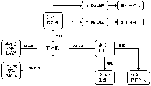
[0031] Such as figure 1 As shown, this embodiment provides a generator rotor shaft end face marking system, including an industrial computer, a barcode scanner, a motion control card, a servo driver, an electric lifting platform, a horizontal sliding platform, a laser marking card, a laser generator, Galvanometer scanning system, the industrial computer is connected to the barcode scanner through the serial port / USB, the industrial computer is connected to the motion control card through the serial port, the motion control card is connected to the servo driver, and the servo driver is connected to the electric lifting platform and the horizontal slide through cables The industrial computer is connected to the laser marking card through the PCI / USB interface, and t...


PUM


Abstract

The invention belongs to the technical field of laser marking, and provides a generator rotor shaft end face marking system and a working method thereof. The system comprises an industrial personal computer, a bar code scanner, a motion control card, a servo driver, an electric lifting platform, a horizontal sliding platform, a laser marking card, a laser generator and a galvanometer scanning system, wherein the industrial personal computer is connected with the bar code scanner through a serial port / USB; the industrial personal computer is connected with the motion control card through a serial port; the motion control card is connected with the servo driver; the servo driver is connected with the electric lifting platform and the horizontal sliding platform through cables; the industrialpersonal computer is connected with the laser marking card through a PCI / USB interface; and the laser marking card is connected with the laser generator and the galvanometer scanning system through cables. The generator rotor shaft end face marking system can effectively realize automatic control and data information management, reduce manual intervention, ensure the data uniqueness of a rotor shaft and improve the production efficiency.

Description

technical field [0001] The invention belongs to the technical field of laser marking, and in particular relates to a marking system for the end face of a generator rotor shaft and a working method thereof. Background technique [0002] At present, many generator manufacturing enterprises pay more and more attention to the marking of parts, so as to facilitate the traceability management of all parts produced. The rotor shaft is the core component of the generator, but few companies have complete production specifications for it. At the same time, since the rotor shaft has many specifications, the design of the tooling is relatively complicated, and the degree of automation and information management is low. After the operator is fatigued from long-term work, it is easy to make mistakes or miss marks on the end face of the rotor shaft. None of the above situations can meet the increasing requirements of users for mass production, automation efficiency, information management...

Claims


Application Information

Patent Timeline
Patent Type & Authority Applications(China)
IPC IPC(8): B41J3/54B41J29/393G06K17/00
CPCB41J3/54B41J29/393G06K17/0022
Inventor 杜伟光丁维书齐飞
Owner 武汉嘉铭激光股份有限公司
Learn More