
Tunnel Supporting Steel Frame and Construction Method in Weak Surrounding Rock

A technology for weak surrounding rock and tunnel, applied in the field of supporting steel frame and construction of weak surrounding rock tunnel, can solve the problems of many operating diseases, reduced work efficiency, small deformation, etc., and achieve good technical benefits, economic benefits, and good economic benefits. and technical benefits, the effect of improving the overall stability

Active Publication Date: 2021-05-25
ZHEJIANG ZHENGFANG TRAFFIC CONSTR CO LTD
View PDF10 Cites 1 Cited by
  • Summary
  • Abstract
  • Description
  • Claims
  • Application Information

AI Technical Summary

Problems solved by technology

However, in engineering practice, it was found that the double-side wall pilot pit method and the partition wall method have the following disadvantages: first, the use of large-scale construction machinery is limited, and work efficiency is reduced; second, in the tunnel construction with soft and hard surrounding rocks, the construction The adjustment time of the method is very long; the third is that there are many temporary construction supports, the investment is large, and it is uneconomical; the fourth is that there is a lot of mutual interference in the construction; the fifth is that the waterproof layer and concrete lining are constructed in parts, and there are many operational defects
Bolt support is the most commonly used measure to control the large deformation of the surrounding rock. However, it is difficult for the traditional bolt to achieve an effective support effect in the large deformation tunnel. The main reason is that the allowable deformation of the traditional bolt is small. When the deformation and deformation of the surrounding rock exceed the bearing range of the traditional bolt, the bolt will be broken and damaged, which will cause the support structure to fail and be destroyed

Method used


Image

  • Tunnel Supporting Steel Frame and Construction Method in Weak Surrounding Rock
  • Tunnel Supporting Steel Frame and Construction Method in Weak Surrounding Rock
  • Tunnel Supporting Steel Frame and Construction Method in Weak Surrounding Rock

Examples


Embodiment Construction

[0037] The present invention will be further described below in conjunction with the examples. The description of the following examples is provided only to aid the understanding of the present invention. It should be pointed out that for those skilled in the art, without departing from the principle of the present invention, some improvements and modifications can be made to the present invention, and these improvements and modifications also fall within the protection scope of the claims of the present invention.

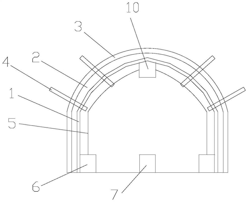
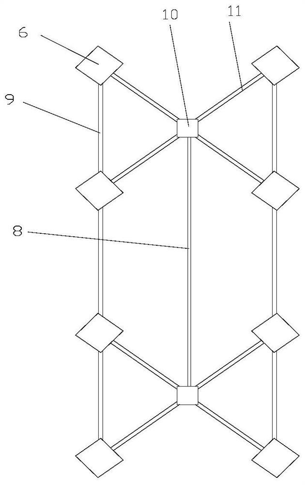
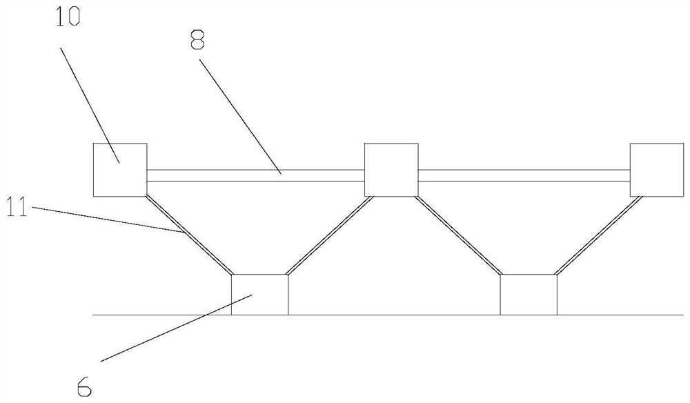
[0038] The supporting steel frame of the weak surrounding rock tunnel includes a lining layer 1, a concrete shotcrete layer 2, an initial support layer 3, an anchor rod 4, a support frame, a drainage system and a top connection steel seat operating platform vehicle; the initial support Layer 3 is located at the outermost layer of the tunnel, the inner side of the primary support layer 3 is the concrete sprayed layer 2, and the inner side of the concrete sprayed la...


PUM


Abstract

The invention relates to a supporting steel frame of a tunnel with weak surrounding rock, including a lining layer, a concrete sprayed layer, an initial supporting layer, an anchor rod, a supporting rigid frame, a drainage system and a top connection steel seat operating platform vehicle; the initial supporting layer is located in the tunnel The outermost layer, the inner side of the primary support layer is the concrete sprayed layer, and the inner side of the concrete sprayed layer is the lining layer; The rigid frames are connected; the drainage system is set on the tunnel ground, and the drainage system includes reserved drainage grooves, drainage grooves and drainers. The beneficial effects of the present invention are: the bolt structure of the present invention has its own monitoring instrument, which can monitor the stability of the overall structure in time, and can provide timely early warning before accidents, so that the construction of the anchor bolt structure is convenient and the structure is simple. There is no need for other excessive structures to play the role of giving way, and it has good economic and technical benefits.

Description

technical field [0001] The invention relates to a supporting steel frame and a construction method, in particular to a supporting steel frame and a construction method for tunnels with weak surrounding rocks. Background technique [0002] With the development of tunnel construction to deeper and more complex strata, there are more and more problems of large deformation of soft rock. With the rapid development of high-grade highways, the construction methods of long-span soft rock highway tunnels are also constantly developing. Side wall pilot pit method, middle partition wall method, etc. However, in engineering practice, it is found that the double-side wall pilot pit method and the partition wall method have the following disadvantages: first, the use of large-scale construction machinery is limited, and work efficiency is reduced; second, in the tunnel construction with soft and hard surrounding rocks, the construction The adjustment time of the method is very long; the ...

Claims


Application Information

Patent Timeline
Patent Type & Authority Patents(China)
IPC IPC(8): E21D11/00E21D11/14E21D21/00E21F16/02B01D29/01B01D29/64
CPCB01D29/01B01D29/6484E21D11/003E21D11/14E21D21/0026E21F16/02
Inventor 龙晓荣徐国卫杨爽张英英
Owner ZHEJIANG ZHENGFANG TRAFFIC CONSTR CO LTD
Learn More