Combined cooling, heating and power micro gas turbine device

A micro gas turbine, combined cooling, heating and power supply technology, applied in gas turbine installations, mechanical equipment, combustion equipment, etc., can solve the problems of large space, large volume, waste of manpower, etc., and achieve compact structure, small volume, and long shaft. minimized effect

Pending Publication Date: 2020-04-28
刘慕华
View PDF0 Cites 7 Cited by
  • Summary
  • Abstract
  • Description
  • Claims
  • Application Information

AI Technical Summary

Problems solved by technology

However, the existing problem is that the existing gas heating equipment has a large volume and occupies a large space. On the other hand, the existing gas heating equipment needs to use a blower to su

Method used


Image

  • Combined cooling, heating and power micro gas turbine device
  • Combined cooling, heating and power micro gas turbine device
  • Combined cooling, heating and power micro gas turbine device

Examples


Embodiment 1

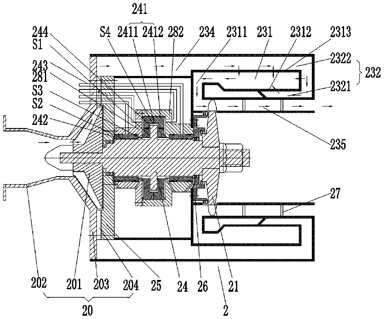
[0100] For this example see figure 1 A thrust disc is set in the middle of the rotating shaft 24 of the micro gas turbine 2, and a thrust bearing 241 is sleeved on the thrust disc; two ends of the rotating shaft 24 are respectively sleeved with radial bearings 242.

[0101] Thrust bearing 241: installed on the rotating shaft 24, including a symmetrically arranged first bearing body 2411 and a second bearing body 2412, the first bearing body 2411 and the second bearing body 2412 are installed symmetrically with the thrust plate in the axial direction and have a predetermined The first axial gap S1; the outer end walls of the first bearing body 2411 and the second bearing body 2412 are respectively provided with a first air groove and a second air groove, and the bottoms of the first air groove and the second air groove are provided with transparent air holes. The air hole communicates with each air groove and the corresponding first axial gap S1; the third radial gap S3 is pres...

Embodiment 2

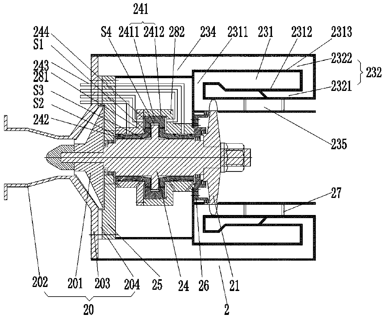
[0108] For this example see figure 2 , On the basis of Embodiment 1, the thrust bearing 241 close to the shaft surface and the radial bearing 242 close to the thrust disk end surface are connected as one; the third radial gap S3 is a tapered gap and shrinks toward the radial bearing 242.

Embodiment 3

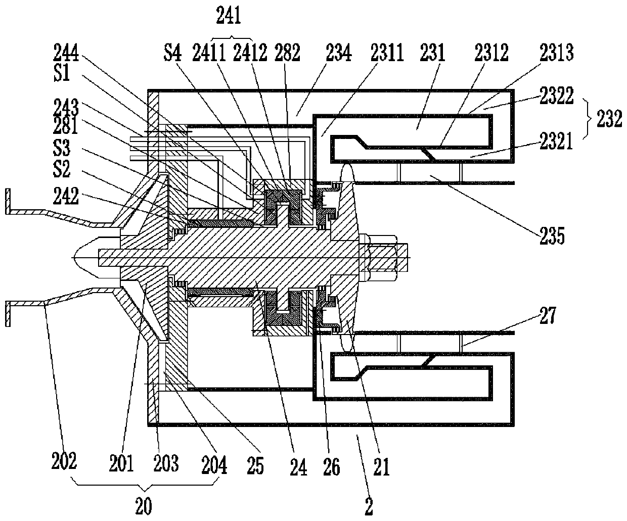
[0110] For this example see image 3 , the rotating shaft 24 of the micro gas turbine 2 is provided with a thrust disc at one end of the turbine 21, and a thrust bearing 241 is sleeved on the thrust disc;

[0111] Thrust bearing 241: installed on the rotating shaft 24, including the first bearing body 2411 and the second bearing body 2412, the first bearing body 2411 and the second bearing body 2412 are installed symmetrically with the thrust plate in the axial direction and have a predetermined first axis To the gap S1; the outer end walls of the first bearing body 2411 and the second bearing body 2412 are respectively provided with a first air groove and a second air groove, and the bottoms of the first air groove and the second air groove are provided with transparent air holes, and the air holes communicate with each other. The air groove and the corresponding first axial gap S1; the preset third radial gap S3 between the inner ring of the first bearing body 2411 and the s...


PUM


Abstract

The invention provides a combined cooling, heating and power micro gas turbine device. The combined cooling, heating and power micro gas turbine device comprises a micro gas turbine; the micro gas turbine comprises a gas compressor, a turbine wheel and a combustion chamber assembly; the combustion chamber assembly comprises a combustion chamber, an air inlet cavity, an air inlet channel and an exhaust channel, the air inlet cavity comprises an internal air inlet cavity and an external air inlet cavity which are integrated, the air outlet end of the external air inlet cavity communicates with the air inlet end of the internal inlet cavity, the air inlet end of the external air inlet cavity communicates with the air inlet channel, the air inlet channel communicates with the gas compressor, the combustion chamber is arranged between the internal air inlet cavity and the external air inlet cavity, and an air outlet of the combustion chamber communicates with the exhaust channel; and an impeller of the gas compressor is coaxially connected with the turbine wheel through a rotating shaft, and the rim of the turbine wheel stretches into the exhaust channel. The combined cooling, heating and power micro gas turbine device has the advantages of being small in size, free of maintenance and high in heat exchange efficiency.

Description

technical field [0001] The invention relates to the technical field related to gas turbines, in particular to a micro gas turbine equipment for triple cooling, heating and power supply. Background technique [0002] The micro gas turbine is a newly developed small heat engine, its stand-alone power ranges from 25 to 300kW, and its basic technical features are radial flow impeller machinery and regenerative cycle. A micro gas turbine mainly includes three major components: a compressor, a combustor and a turbine. After entering the compressor, the air is compressed into high-temperature and high-pressure air, which is then supplied to the combustion chamber for mixed combustion with fuel, and the high-temperature and high-pressure gas generated expands in the turbine to perform work. The micro gas turbines in the prior art are bulky and not compact enough to ensure high heat exchange efficiency and stable operation at high speeds. [0003] Micro gas turbines can be used for...

Claims


Application Information

Patent Timeline
IPC IPC(8): F02C3/14F02C6/00F02C6/18F01D15/10F04D29/056F23R3/04
CPCF02C3/14F02C6/00F02C6/18F01D15/10F04D29/056F23R3/04F05D2250/82F01D25/22F05D2240/52F05D2240/54F23R3/50F23R3/54F02C3/04F02C7/06F02C7/12F05D2220/64F05D2220/76
Inventor 靳普
Owner 刘慕华
Why Eureka
Try Eureka