
Noise equivalent temperature difference device of thermal infrared imager with ultra-large field of view and test method

A noise equivalent temperature difference, infrared thermal imaging camera technology, applied in the field of infrared imaging, can solve the problem of not considering the impact, etc., to achieve the effect of improving accuracy

Active Publication Date: 2020-04-28
LUOYANG INST OF ELECTRO OPTICAL EQUIP OF AVIC
View PDF5 Cites 2 Cited by
  • Summary
  • Abstract
  • Description
  • Claims
  • Application Information

AI Technical Summary

Problems solved by technology

[0011] 3) The signal transfer function of the infrared system is the ratio of the signal value corresponding to the temperature difference between the target and the background and the temperature difference between the target and the background. Due to the test environment and test equipment, the signal transfer function has a certain deviation
Traditional test equipment only uses temporal high-frequency noise to characterize the noise information of the infrared imaging system, without considering the influence of other components on the infrared imaging system

Method used


Image

  • Noise equivalent temperature difference device of thermal infrared imager with ultra-large field of view and test method
  • Noise equivalent temperature difference device of thermal infrared imager with ultra-large field of view and test method
  • Noise equivalent temperature difference device of thermal infrared imager with ultra-large field of view and test method

Examples


Embodiment Construction

[0037] The present invention will be further described below in conjunction with the accompanying drawings and embodiments.

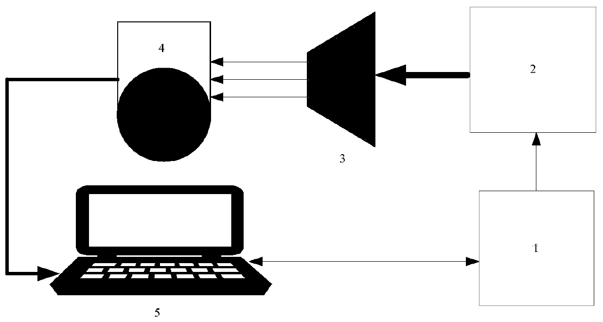
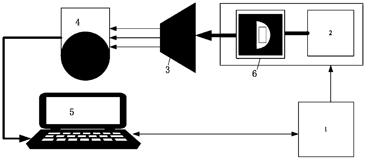
[0038] A noise-equivalent temperature difference device for a super-large field of view infrared thermal imager, including a blackbody controller, a blackbody radiation source, a collimator light pipe, an infrared imaging system and a low-voltage differential signal acquisition industrial computer, the blackbody controller is connected to the blackbody radiation source, and the blackbody radiation The source provides radiant energy, and through the collimated light tube, the incident light source of the black body is converted into a parallel light source and enters the infrared imaging system. The infrared imaging system collects grayscale data, and controls the temperature of the blackbody radiation source through the blackbody controller.

[0039] The test method of the noise equivalent temperature difference device of the super large field of view i...


PUM


Abstract

The invention provides a noise equivalent temperature difference device of a thermal infrared imager with an ultra-large field of view and a test method. A blackbody controller is connected with a blackbody radiation source, the blackbody radiation source provides the radiation energy; a light source incident from a black body is converted into a parallel light source through a collimating light tube to enter an infrared imaging system; the infrared imaging system is aligned with the center of the view field of the collimating light tube and transmits test data to an industrial personal computer; the industrial personal computer collects gray scale data from the infrared imaging system; and temperature control is conducted on the black body radiation source through the black body controller. According to the invention, the problem that the equivalent temperature difference of the infrared noise with the ultra-large field of view cannot be tested is solved and a test result meeting theprecision requirement is obtained; a three-dimensional noise model is introduced and time noise and space noise are subdivided into seven components, so that the noise of the infrared imaging system is comprehensively evaluated. According to the invention, the original gray scale data are sampled without being influenced by an image processing algorithm, so that the test accuracy is effectively improved.

Description

technical field [0001] The invention relates to the field of infrared imaging, in particular to a noise equivalent temperature difference device and a testing method for an infrared imaging system. Background technique [0002] The infrared imaging system obtains the heat map distribution of the target and the background by detecting the infrared radiation characteristics. The noise equivalent temperature difference is one of the main performance parameters of the infrared imaging system, which can characterize the temperature sensitivity of the system to the target. Through the laboratory data test of the noise equivalent temperature difference, the working distance of the infrared imaging system can be evaluated. [0003] Traditional noise equivalent temperature difference test equipment includes black body radiation source, target target plate, collimated light pipe, analog video acquisition equipment, calculation software and monitor. The schematic diagram of the test ...

Claims


Application Information

Patent Timeline
IPC IPC(8): G01J5/00G01J5/52
CPCG01J5/00G01J2005/0077G01J5/53
Inventor 梁锡宁余晨菲郭晨龙杜保林郑国锋
Owner LUOYANG INST OF ELECTRO OPTICAL EQUIP OF AVIC
Learn More