Material outboard annular inspection driving mechanism and annular inspection mechanism

A driving mechanism and an outer ring technology are applied in the field of the outer ring inspection drive mechanism and the ring inspection mechanism of the material cabin, which can solve the problem of real-time monitoring of the surface morphology of the exposed material, etc. Avoid the effect of transmission jamming or failure

Active Publication Date: 2020-05-01
TECH & ENG CENT FOR SPACE UTILIZATION CHINESE ACAD OF SCI
View PDF8 Cites 2 Cited by
  • Summary
  • Abstract
  • Description
  • Claims
  • Application Information

AI Technical Summary

Problems solved by technology

[0024] The technical problem to be solved by the present invention is that there is currently no on-orbit detection mechanism f

Method used


Image

  • Material outboard annular inspection driving mechanism and annular inspection mechanism
  • Material outboard annular inspection driving mechanism and annular inspection mechanism
  • Material outboard annular inspection driving mechanism and annular inspection mechanism

Examples


Embodiment 1

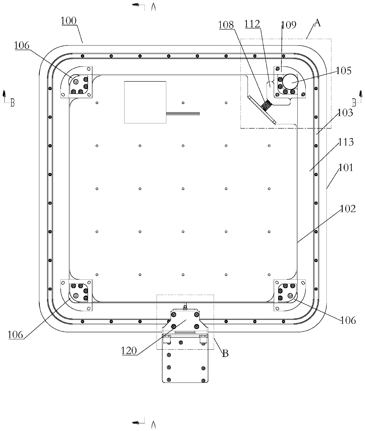
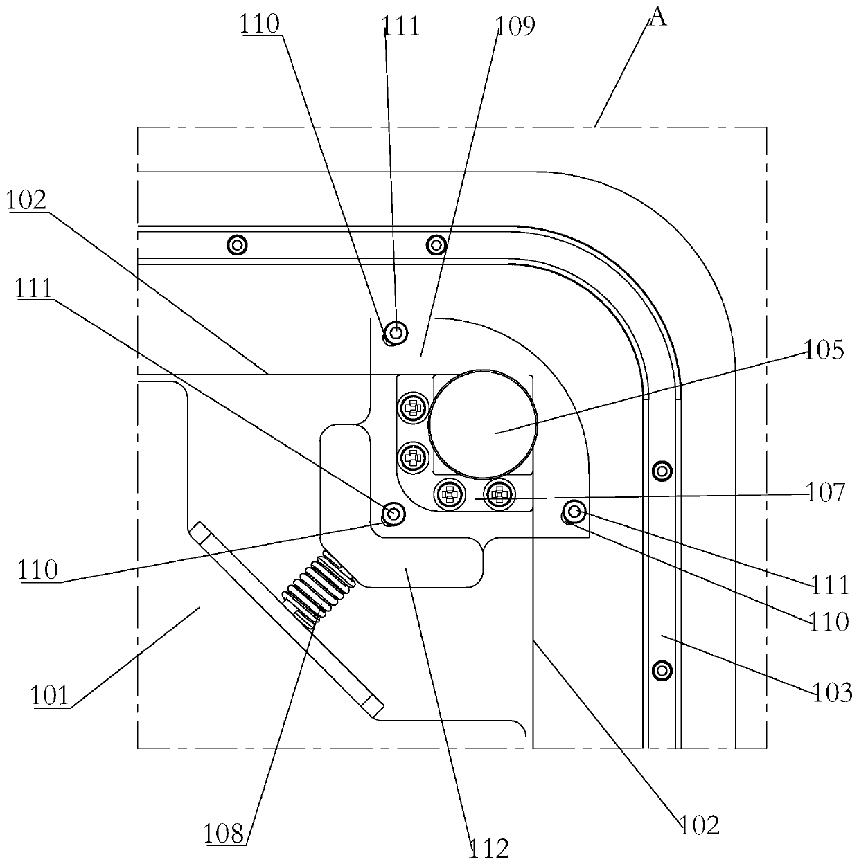
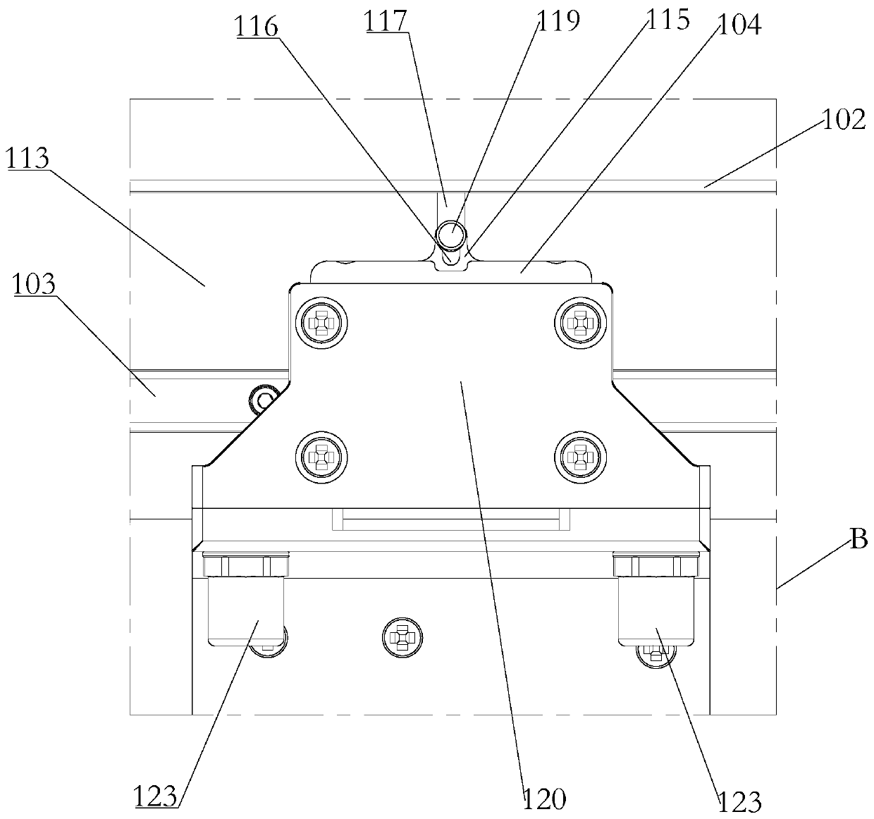
[0070] Such as Figure 1-Figure 5 As shown, a ring-shaped inspection drive mechanism outside the material compartment of this embodiment includes:

[0071] Installation platform 101 on which is provided with a steel belt drive mechanism;

[0072] An endless steel belt 102 is looped around the installation platform 101, and is driven by the steel belt drive mechanism to make a circular motion around the circumference of the installation platform 10;

[0073] The annular guide rail 103 is arranged around the installation platform 101 and is located on the outer peripheral side of the annular steel belt 102; the annular guide rail provides bearing and guidance for the annular inspection device, and is composed of a linear section guide rail and a curved section guide rail. The curved section guide rail is mainly adapted to the corner of the installation platform to realize the circular movement of the circular inspection device;

[0074] The carrying slider 104 for carrying the annular i...

Embodiment 2

[0097] Such as Figure 6-Figure 9 As shown, a material outer ring inspection mechanism of this embodiment includes the ring inspection drive mechanism 100 and the ring inspection device. The ring inspection device includes a mounting bracket 301 and a vertical drive mechanism. The mounting bracket 301 is mounted on the carrying slider 104, and the optical inspection module 200 is mounted on the vertical driving mechanism and moves up and down under the drive of the vertical driving mechanism; the vertical driving mechanism is a vertical steel Belt drive mechanism 300.

[0098] Among them, such as Figure 6-Figure 9 As shown, the vertical steel belt drive mechanism 300 includes a vertical steel belt drive motor 302, a steel belt wheel one, a steel belt wheel two, a steel belt wheel support one 303, a steel belt wheel support two 304 and a vertical drive steel belt 306, The mounting bracket 301 is arranged vertically and the bottom is connected with the vertical side wall of the ...


PUM


Abstract

The invention relates to a material outboard annular inspection driving mechanism and an annular inspection mechanism. The annular inspection driving mechanism comprises an installation platform whichis provided with a steel belt driving mechanism, an annular steel belt which is annularly arranged on the periphery of the installation platform and annularly moves around the peripheral side of theinstallation platform under the driving of the steel belt driving mechanism, an annular guide rail which is annularly arranged on the periphery of the installation platform and located on the peripheral side of the annular steel belt, and a bearing sliding block which is used for bearing the annular inspection device, is connected to the annular steel belt and is arranged on the annular guide railin a sliding manner. The annular inspection device can be driven to do annular motion around the installation platform, and the surface topography motion of an exposed material on the installation platform can be monitored in real time; an annular steel belt is used for transmission, the weight is light, the occupied space is small, and the weight and space resources are greatly saved; the steelbelt is low in thermal expansion coefficient, has the characteristic of small deformation quantity at high and low temperatures, can well adapt to the material outboard complex space environment, andavoids the situation of transmission jamming or failure.

Description

Technical field [0001] The invention relates to the related field of aerospace material exposure, in particular to a material outer-vehicle circular inspection drive mechanism and a circular inspection mechanism. Background technique [0002] In space research, the development of space technology and space science is inseparable from the use of various materials, especially new materials. The study of material space service behavior is to conduct space environment exposure experiments for all materials in service in space environment and the parts, devices, components, components and equipment made of them. The purpose is to study the effects of materials under special environmental effects in space. Causative behavior. In order to ensure the stability, reliability and durability of materials and their products in the process of space service, it is necessary to conduct in-depth research on the service behavior of materials in the space environment. Among them, the material exp...

Claims


Application Information

Patent Timeline
IPC IPC(8): B64G1/66G01N17/00
CPCB64G1/66G01N17/00G01N17/004
Inventor 张伟贵张聚乐王乐天王珂杨鹏邓明哲郭志奇
Owner TECH & ENG CENT FOR SPACE UTILIZATION CHINESE ACAD OF SCI
Why Eureka
Try Eureka