Optical power automatic calibration system and method

An automatic calibration, optical power technology, applied in the field of optical communication, can solve the problems of inconvenient operation, cumbersome test process, multiple devices, etc., to achieve the effect of small space occupation and shortening of manual adjustment time

Inactive Publication Date: 2020-05-05
上海传输线研究所
View PDF8 Cites 4 Cited by
  • Summary
  • Abstract
  • Description
  • Claims
  • Application Information

AI Technical Summary

Problems solved by technology

[0005] In order to well overcome the problems in the prior art that calibration requires multiple devices, inconvenient operation, cumbersome testing process, and

Method used


Image

  • Optical power automatic calibration system and method
  • Optical power automatic calibration system and method
  • Optical power automatic calibration system and method

Examples


Example Embodiment

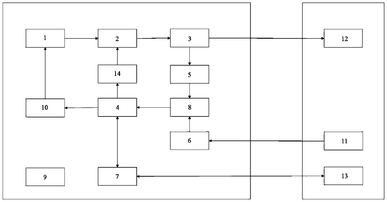
[0051] A new type of optical power automatic calibration system proposed by the present invention has a structure such as figure 1 As shown, it consists of light source module 1, electrical modulation attenuator 2, one-in-two-out beam splitter 3, micro-control unit MCU4, output photodetector 5, input photodetector 6, system serial interface 7, ADC analog-to-digital conversion Module 8, temperature detection control circuit 9, current drive circuit 10, and analog voltage control circuit 14.

[0052] The optical output terminal 11 of the module to be tested is connected to the input photodetector 6. The input photodetector 6 is connected to the microcontroller MCU4 through the ADC analog-to-digital conversion module 8. The first end of the microcontroller MCU4 is connected to the temperature detection control circuit 9. The second end of the microcontroller unit MCU4 is connected to the current drive circuit 10 to control the wavelength of the light source module 1, the light sourc...


PUM


Abstract

The invention relates to the technical field of optical communication, in particular to an optical power automatic calibration system and method. The system is characterized in that the system comprises a light source module 1, an electric modulation attenuator 2, a one-input two-output light beam splitter 3, a micro control unit MCU4, an output photoelectric detector 5, an input photoelectric detector 6, a system serial interface 7, an ADC analog-to-digital conversion module 8, a temperature detection control circuit 9, a current driving circuit 10 and an analog voltage control circuit 14. According to the novel optical power automatic calibration system and method provided by the invention, a PID system with built-in control detection is adopted, so that the output optical power is prevented from drifting and distorting. Output and input of optical power are adjusted in a full-automatic mode, and the manual adjusting time is greatly shortened. Functions of a light source, a power meter, an attenuator and the like are integrated into a set of system and are controlled by a micro-control unit, so that the occupied space is small, and the testing method is simple.

Description

technical field [0001] The invention relates to the technical field of optical communication, in particular to an optical power automatic calibration system and method. Background technique [0002] With the advent of the 5G era, the optical fiber communication network has been greatly developed. Active optical fiber communication equipment such as light sources, optical power meters, optical fiber amplifiers, and optical modules have become indispensable instruments and equipment in optical fiber communication and testing. It has important applications in the fields of large-scale construction and maintenance, multi-input and output testing of optical fiber arrays, and mass testing of optical active and passive devices. In order to improve the optical power accuracy of optical communication equipment, it is necessary to calibrate the input and output optical power of optical communication equipment before leaving the factory. However, due to the uncertainty of the working ...

Claims


Application Information

Patent Timeline
IPC IPC(8): G01J1/44G01J1/08
CPCG01J1/08G01J1/44G01J2001/086G01J2001/444
Inventor 张翔陈涛汪衍景金操帆
Owner 上海传输线研究所
Why Eureka
Try Eureka