
Capacitance tomography sensor and system

A capacitance tomography and sensor technology, applied in the field of sensors, can solve the problems of non-reusable, inconvenient replacement, maintenance, and difficult sensor installation, etc., and achieve the effects of reducing test costs, convenient manufacturing process, and easy maintenance

Pending Publication Date: 2020-05-05
DALIAN INST OF CHEM PHYSICS CHINESE ACAD OF SCI
View PDF4 Cites 1 Cited by
  • Summary
  • Abstract
  • Description
  • Claims
  • Application Information

AI Technical Summary

Problems solved by technology

[0004] However, the measuring electrodes of traditional ECT sensors are not detachably fixed on the outer wall of the test pipe, the manufacturing process is very cumbersome, especially when the sensor needs to be installed on site, it is often difficult to install; and it cannot be reused, which reduces the test efficiency and improves The cost of testing; and the various components of the sensor are not detachably fixed, so when one of the components is damaged, the sensor can only be remade, which is time-consuming and laborious, and it is not easy to replace and maintain

Method used


Image

  • Capacitance tomography sensor and system
  • Capacitance tomography sensor and system
  • Capacitance tomography sensor and system

Examples


Embodiment 1

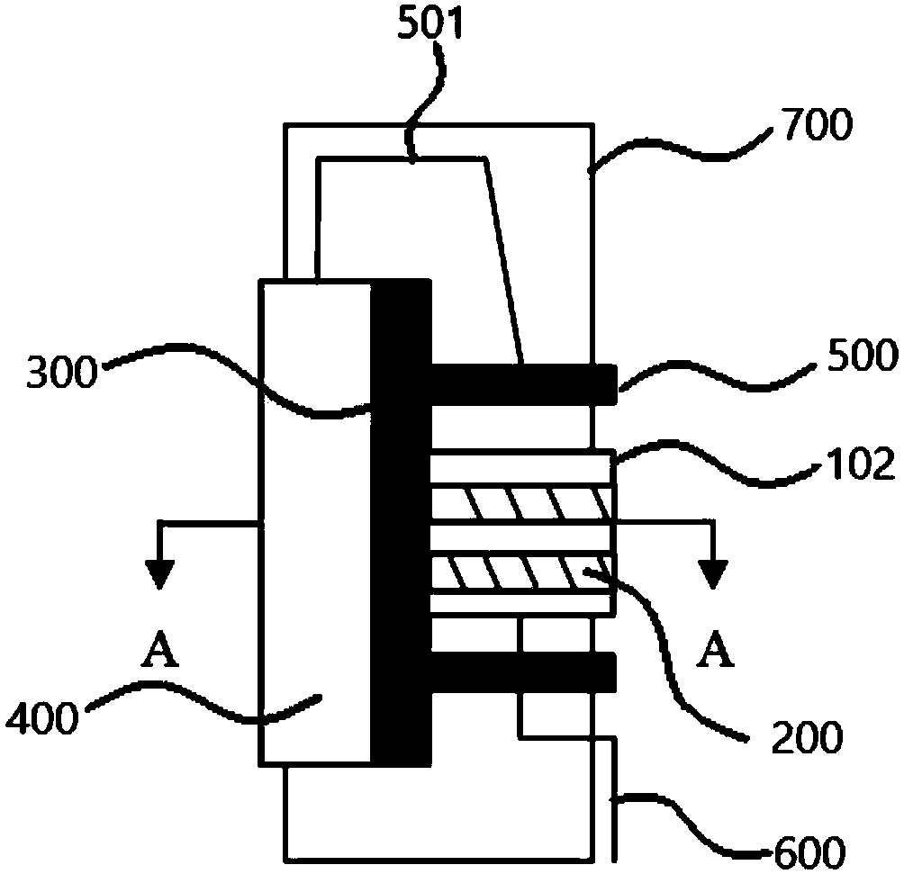
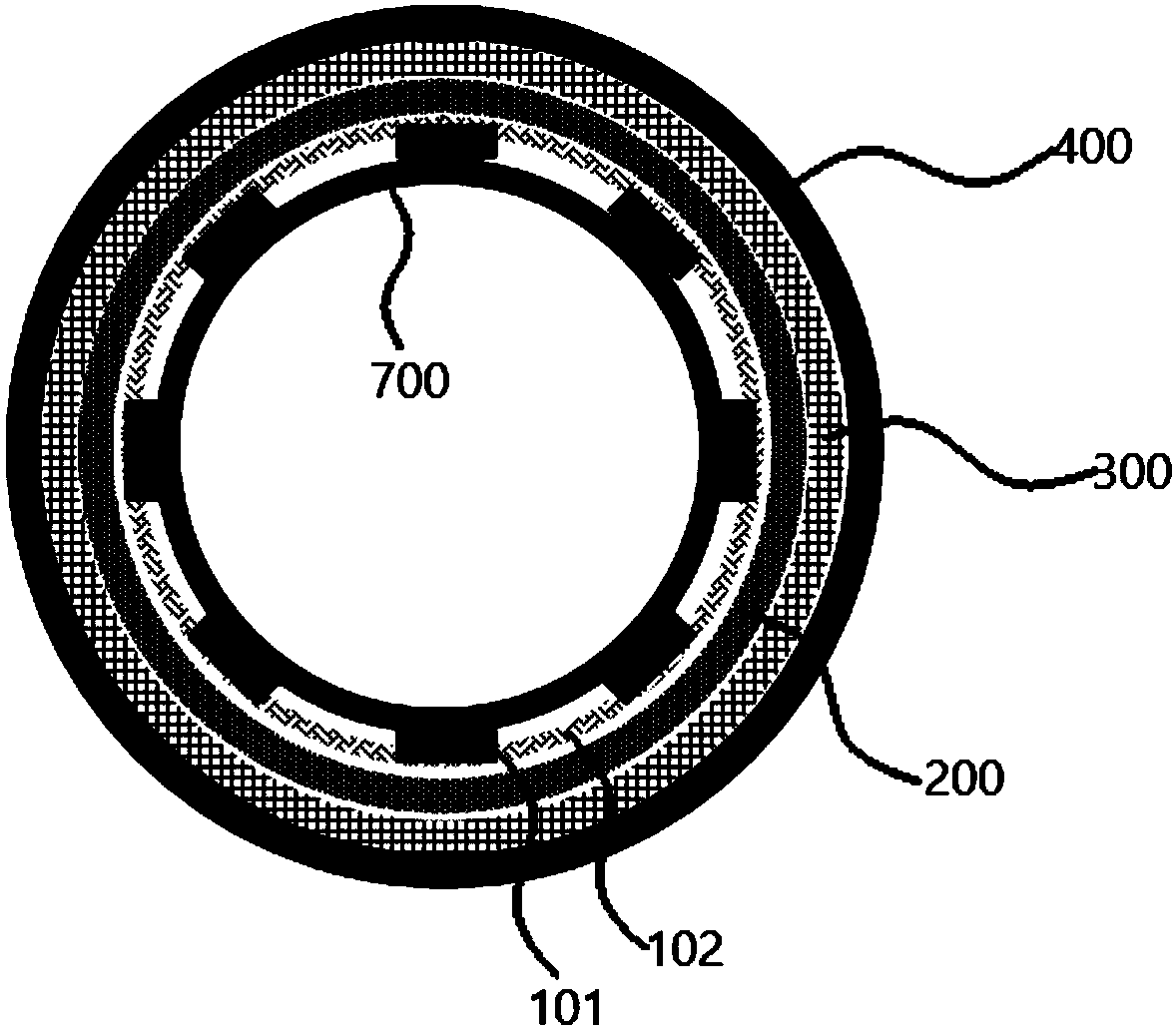
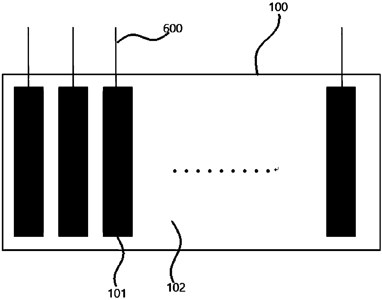
[0034] figure 1 It is a schematic structural diagram of an electrical capacitance tomography sensor in an embodiment of the present application, figure 2 for figure 1 A transverse cross-sectional view of the electrical capacitance tomography sensor shown in A-A direction, image 3 It is a schematic structural diagram of a flexible electrode assembly in an electrical capacitance tomography sensor in an embodiment of the present application, Figure 4 It is a schematic structural diagram of a fixing member in an embodiment of the present application, combined below Figure 1~4 The implementation of this embodiment will be described in detail.

[0035] The electrical capacitance tomography sensor provided in this application includes a flexible electrode assembly 100, a fixing member 200, an insulating isolation layer 300, and an outer shield 400;

[0036] The flexible electrode assembly 100 includes an array electrode 101 and a flexible carrier 102, and the array electrode ...

Embodiment 2

[0063] The following describes the fabrication process of the electrical capacitance tomography sensor provided by the present application.

[0064] In this embodiment, the arrayed electrodes 101 are evenly pasted on the flexible carrier 102 at fixed intervals, and the single electrodes of the arrayed electrodes 101 are not in contact with each other. The flexible carrier 102 is wound on the outer surface of the measured object 700, so that the array distribution electrodes 101 are attached to the surface of the measured object 700 and evenly distributed around the measured area. Fix the shaft-end shielding electrode 500 on the surface of the measured object 700 at the upper and lower axial ends of the array electrode 101, and use the fixing member 200 to fix the flexible carrier 102 and the array electrode 101 on the outer surface of the measured object 700 to prevent measurement During the process, the array electrode 101 moves. The outer side of the flexible carrier 102 an...

Embodiment 3

[0068] This embodiment provides a capacitance tomography system, including a signal acquisition system, a computer imaging display system, and any of the capacitance tomography sensors described above. The capacitance tomography sensor is connected to the signal acquisition system through a signal output line 600, so that The signal acquisition system is connected with the computer imaging display system.

[0069] In this application, the signal transmission line 600 transmits the electrode signal detected by the array electrode 101 to the signal acquisition system, and then transmitted to the computer imaging display system through the data acquisition card in the signal acquisition system to complete image reconstruction.


PUM


Abstract

The invention discloses a capacitance tomography sensor which comprises a flexible electrode assembly, a fixing component, an insulation isolation layer and an outer shielding cover. The flexible electrode assembly comprises an array type electrode and a flexible carrier, and the array type electrode is fixed along the inner circumferential wall of the flexible carrier. The fixing component is detachably mounted on the outer peripheral wall of the flexible carrier, so that the array type electrodes are detachably enclosed on the outer peripheral wall of a tested object to perform capacitance test on fluid in the tested object. The insulating isolation layer is detachably fixed on the outer peripheral wall of the fixing component. The outer shielding cover is detachably fixed on the outer peripheral wall of the insulating isolation layer. The capacitance tomography sensor provided by the invention can be detachably mounted, and is very convenient to manufacture on site, so that the testefficiency is improved, and the test cost is reduced. Each part in the sensor can be replaced, so that the maintenance of the sensor is facilitated, and the use cost is also reduced.

Description

technical field [0001] The application relates to an electric capacitance tomography sensor and system, belonging to the technical field of sensors. Background technique [0002] Electrical capacitance tomography (ECT) is a kind of process tomography technology, which was formed and developed on the basis of medical CT technology in the late 1980s. Its basic working principle is: according to the different dielectric constants of the measured substances, when the composition or concentration of the measured mixture changes, the dielectric constant of the mixture will change, and finally the capacitance value measured by the capacitive sensor will change. Then, based on the measured capacitance value, the inverse problem in the electromagnetic field is used to solve the problem, and the dielectric constant distribution inside the industrial process equipment such as closed pipes and containers is obtained, and two-dimensional / three-dimensional visualization is realized. ECT ...

Claims


Application Information

Patent Timeline
Patent Type & Authority Applications(China)
IPC IPC(8): G01N27/22
CPCG01N27/221
Inventor 赵银峰叶茂孟霜鹤张涛刘中民
Owner DALIAN INST OF CHEM PHYSICS CHINESE ACAD OF SCI
Learn More