Gear finish machining grinding positioning mechanism

A positioning mechanism and grinding machine technology, which is applied to gear cutting machines, metal processing equipment, gear tooth manufacturing devices, etc., can solve problems such as difficult operation, positioning accuracy size deviation, and inconvenient processing, so as to reduce labor intensity and high degree of automation , high processing efficiency

Active Publication Date: 2020-05-08
浙江陆鑫门控设备有限公司
View PDF5 Cites 11 Cited by
  • Summary
  • Abstract
  • Description
  • Claims
  • Application Information

AI Technical Summary

Problems solved by technology

Then the finished gear needs to be accurately and effectively fixed on the machine tool for grinding and processing. However, the clamping and fixing methods currently used mainly include: external pressure plate fixing, mandrel spline fixing, and magnetic chuck fixing. The above methods exist to varying degrees. Due to the influence of fixtures, processing is inconvenient. In addition, due to processing errors affecting positioning accuracy, subsequent dimensional deviations, and manual clamping and alignment are complicated and difficult to operate. These problems affect product quality and production efficiency.

Method used


Image

  • Gear finish machining grinding positioning mechanism
  • Gear finish machining grinding positioning mechanism
  • Gear finish machining grinding positioning mechanism

Examples


Embodiment Construction

[0031] The present invention will be further described below in conjunction with specific embodiments. The exemplary embodiments and descriptions of the present invention are used to explain the present invention, but not as a limitation to the present invention.

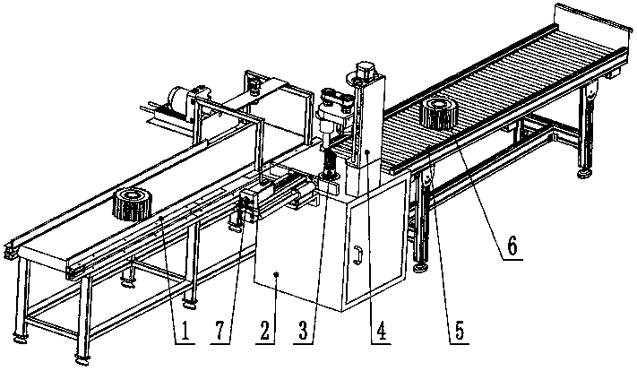
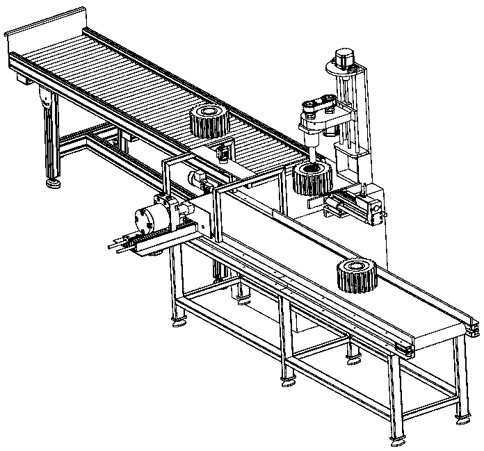
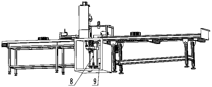
[0032] Such as figure 1 , figure 2 , image 3 , Figure 4 Shown is a gear processing deburring device. Including feeding device 1, fixed worktable 2, adjustable positioning device 3, grinding machine 4, unloading roller table 5, workpiece gear 6, unloading and pushing device 7, lifting mechanism 8, hydraulic station 9, fixed working table 2 It is a box-type frame structure, fixedly installed on the ground, with a movable door on the side, the grinding machine 4 is fixedly installed on one side of the upper plane of the fixed workbench 2, and the feeding and pushing device 7 is fixedly installed on the other side of the fixed workbench 2 On the side, its bottom surface is flush with the upper plane of the fixed ...


PUM


Abstract

The invention discloses a gear finish machining grinding positioning mechanism, which comprises a feeding device, a fixed workbench, an adjustable positioning device, a grinder, a discharging roller bed, a workpiece gear, a discharging and pushing device, a lifting mechanism and a hydraulic station. The box type workbench is fixedly installed on the ground, and the box body of the workbench is provided with a set of lifting mechanism and hydraulic system; the adjustable positioning device is fixedly installed on a lifting sliding seat of the lifting mechanism, can move up and down in the central hole of the upper table of the fixed workbench with movement of the sliding seat, and is used for machining and positioning of gears; the grinder is fixedly installed on the upper face of the workbench, and a set of pushing device used for moving out finished products is further arranged on the side face of the workbench; and workblank of the workpiece gear is transmitted to the fixed workbenchthrough the feeding device, and then a finished product is transported to a next station through the discharging roller bed after being processed through positioning of the adjustable positioning device. The mechanism is arranged in line, degree of automation is high, positioning is precise and reliable, the processing quality can be effectively guaranteed, and the production efficiency is improved.

Description

technical field [0001] The invention relates to the technical field of mechanical fixtures, in particular to a positioning mechanism for gear finish machining and grinding. Background technique [0002] The flanging or burr produced by gear processing is traditionally processed by manual grinding with sand belt or file. With the continuous improvement of processing automation, this process has also begun to use machine tools for grinding and removal. Then the finished gear needs to be accurately and effectively fixed on the machine tool for grinding and processing. However, the clamping and fixing methods currently used mainly include: external pressure plate fixing, mandrel spline fixing, and magnetic chuck fixing. The above methods exist to varying degrees. Due to the influence of fixtures, processing is inconvenient. In addition, due to processing errors affecting positioning accuracy, subsequent dimensional deviations, and manual clamping and alignment are complicated an...

Claims


Application Information

Patent Timeline
Patent Type & Authority Applications(China)
IPC IPC(8): B23F19/00B23F23/04B23F23/06B24B21/00B24B41/00B24B41/06B24B49/00
CPCB23F19/00B23F23/04B23F23/06B24B21/002B24B41/005B24B41/06B24B49/00
Inventor 董红媛赵汉章
Owner 浙江陆鑫门控设备有限公司
Why Eureka
Try Eureka