Mold filling device for ferrite soft magnetic core production

A soft magnetic core, ferrite technology, applied in the direction of manufacturing tools, ceramic molding machines, etc., can solve the problems of manpower consumption and low efficiency, and achieve the effect of improving efficiency, avoiding air bubbles, and improving versatility

Active Publication Date: 2020-05-08
天长市联嘉磁电科技有限公司
View PDF8 Cites 2 Cited by
  • Summary
  • Abstract
  • Description
  • Claims
  • Application Information

AI Technical Summary

Problems solved by technology

[0004] The purpose of the present invention is to solve the problems of labor-intensive and low efficiency in the prior art, and propose a mold filling device for ferrite soft magnetic core production

Method used


Image

  • Mold filling device for ferrite soft magnetic core production
  • Mold filling device for ferrite soft magnetic core production
  • Mold filling device for ferrite soft magnetic core production

Examples


Embodiment 1

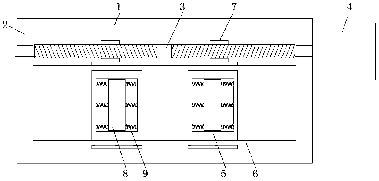
[0022] refer to Figure 1-4 , a mold filling device for ferrite soft magnetic core production, comprising a working base plate 1, both ends of the top side of the working base plate 1 are fixedly connected with vertical plates 2, and two-way threaded rods 3 are arranged for rotation between the vertical plates 2, vertically One side of the plate 2 is fixed with a motor 4 by bolts, the output shaft of the motor 4 is connected to the two-way threaded rod 3 in transmission, and a sliding table 5 and a track bar 6 are also arranged between the two vertical plates 2, and the track bar 6 The two ends are fixedly connected to one side of the vertical plate 2 respectively. There are two sliding tables 5, and both of them are provided with slide holes and are all slidably sleeved on the outside of the rod body of the track rod 6. The outside of the rod body of the two-way threaded rod 3 is provided with two ends. The threaded grooves with opposite textures are threadedly connected with...

Embodiment 2

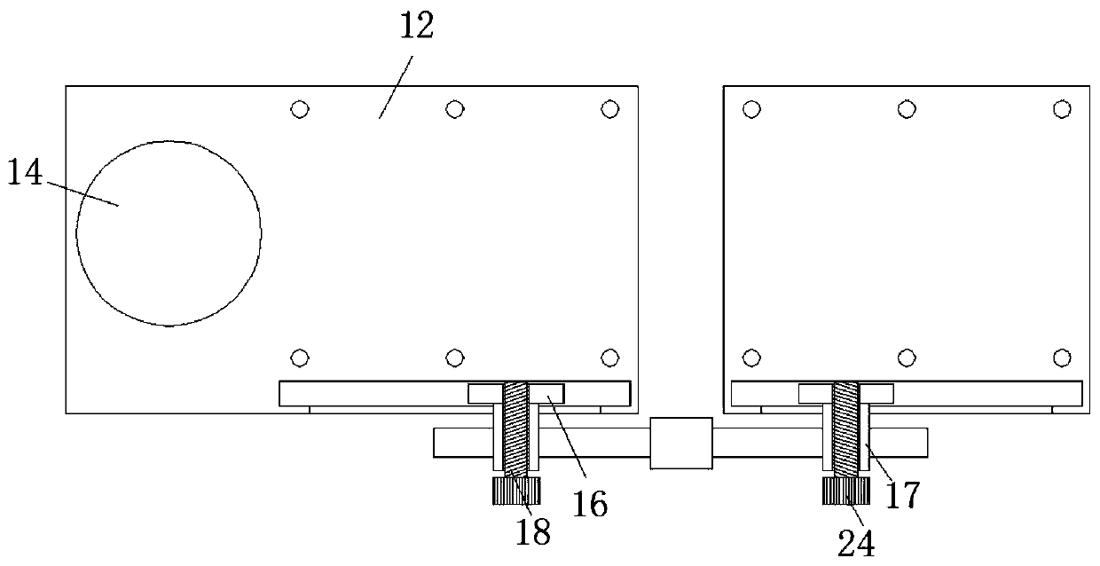
[0026] Such as Figure 1-4 As shown, this embodiment is basically the same as Embodiment 1. Preferably, one end of the fixed threaded column 18 is fixedly connected with a knob 24 , and the knob 24 is provided with anti-slip grooves.

[0027] In this embodiment, the setting of the anti-slip grooves is convenient for people to turn the knob 24. By turning the knob 24, people can make the side slide plate 16 and the threaded force receiving cylinder 17 maintain a relatively stable position with the installation table 12, and when installing molds of different lengths After the body 13 is separated, the initial position of the threaded force receiving cylinder 17 is different, so it needs to be adjusted so that the distance to push the swash plate 23 upward is effective.

Embodiment 3

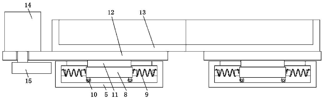
[0029] Such as Figure 1-4 As shown, this embodiment is basically the same as Embodiment 1. Preferably, rollers 10 are provided at the four corners of the bottom of the inner slide 8 .

[0030] In this embodiment, the arrangement of the rollers 10 effectively reduces the frictional force and energy consumption.


PUM


Abstract

The invention discloses a mold filling device for ferrite soft magnetic core production. The device comprises a working bottom plate, wherein vertical plates are fixedly connected to the two ends of the top side of the working bottom plate, a bidirectional threaded rod is rotatably arranged between the vertical plates, one side of one vertical plate is fixedly provided with a motor I through a bolt, an output shaft of the motor I is in transmission connection with the bidirectional threaded rod, sliding tables and track rods are further arranged between the two vertical plates, the two ends ofthe track rods are fixedly connected with one sides of the vertical plates, the sliding tables are provided with sliding holes and both slidably sleeve the outer sides of rod bodies of the track rods, two-end threaded grooves with opposite threads are formed in the outer side of a rod body of the bidirectional threaded rod, and are in threaded connection with threaded barrels, and one sides of the two sliding tables are fixedly connected with the threaded barrels. According to the device, generation of bubbles in a filling process is avoided, the filling effect is better, the processing effect is improved, the production efficiency is improved, and the use requirements of people in production and life are met.

Description

technical field [0001] The invention relates to the technical field of ferrite soft magnetic core production equipment, in particular to a mold filling device for ferrite soft magnetic core production. Background technique [0002] Ferrite cores are mainly composed of three metal elements: iron (Fe), manganese (Mn), and zinc (Zn), and are usually called manganese-zinc ferrite. Toroidal ferrite cores have a high magnetic effect because they have no air gap and have a uniform cross-sectional area. There are many specifications and sizes of ferrite magnetic rings, which can be selected according to the different materials of the magnetic rings, and different coatings can be used to simplify winding and increase breakdown voltage. [0003] During the production process of the existing ferrite core, the alloy liquid needs to be poured into the mold, but in the process of pouring the liquid, some air bubbles are often formed in the mold, and after cooling and forming, It will ca...

Claims


Application Information

Patent Timeline
Patent Type & Authority Applications(China)
IPC IPC(8): B28B7/00B28B1/087
CPCB28B1/0873B28B7/00
Inventor 吴建芳余建达胡明途
Owner 天长市联嘉磁电科技有限公司
Why Eureka
Try Eureka