Novel conveying equipment for garment production

A technology of conveying equipment and clothing, applied in the field of conveying equipment for new clothing production, can solve the problems of easy deformation of clothing, increase the production cost of manufacturers, inability to match clothing, etc., and achieve the effect of clean and complete dust removal and not easy to slip

Active Publication Date: 2020-05-08
潜江东颢制衣有限公司
View PDF5 Cites 7 Cited by
  • Summary
  • Abstract
  • Description
  • Claims
  • Application Information

AI Technical Summary

Problems solved by technology

[0002] After the garment is sewn, the residual thread and plush on the surface need to be removed and then ironed and packaged. With the development of economy and technology, the production of garments has become more and more automated, and the garments are often sent to the next through the conveyor line. One-step processing, because the hanging conveyor line has the advantages of small space occupation, labor saving and high work efficiency, the existing garment production process usually uses the hanging conveyor line for clothing transmission, but because the hanging conveyor in the prior art The line usually uses hooks to fix the clothes, which makes the clothes easily deformed, and the hanging conveyor line only plays the role of transmission, and cannot cooperate with a series of processing steps such as dust removal, ironing, and packing of the clothes, so that the clothes The production line is extremely long and requires a wide area of ​​space, which also wastes energy and reduces production efficiency, thereby increasing the production cost of the manufacturer. Moreover, after each step of clothing is completed, the staff needs to pick and place it, which greatly Increased time and labor costs

Method used


Image

  • Novel conveying equipment for garment production
  • Novel conveying equipment for garment production
  • Novel conveying equipment for garment production

Examples


Embodiment Construction

[0017] In order to make the purpose, technical solutions and advantages of the embodiments of the present invention clearer, the technical solutions in the embodiments of the present invention will be clearly and completely described below in conjunction with the drawings in the embodiments of the present invention. Obviously, the described embodiments It is a part of embodiments of the present invention, but not all embodiments. Based on the embodiments of the present invention, all other embodiments obtained by persons of ordinary skill in the art without creative efforts fall within the protection scope of the present invention.

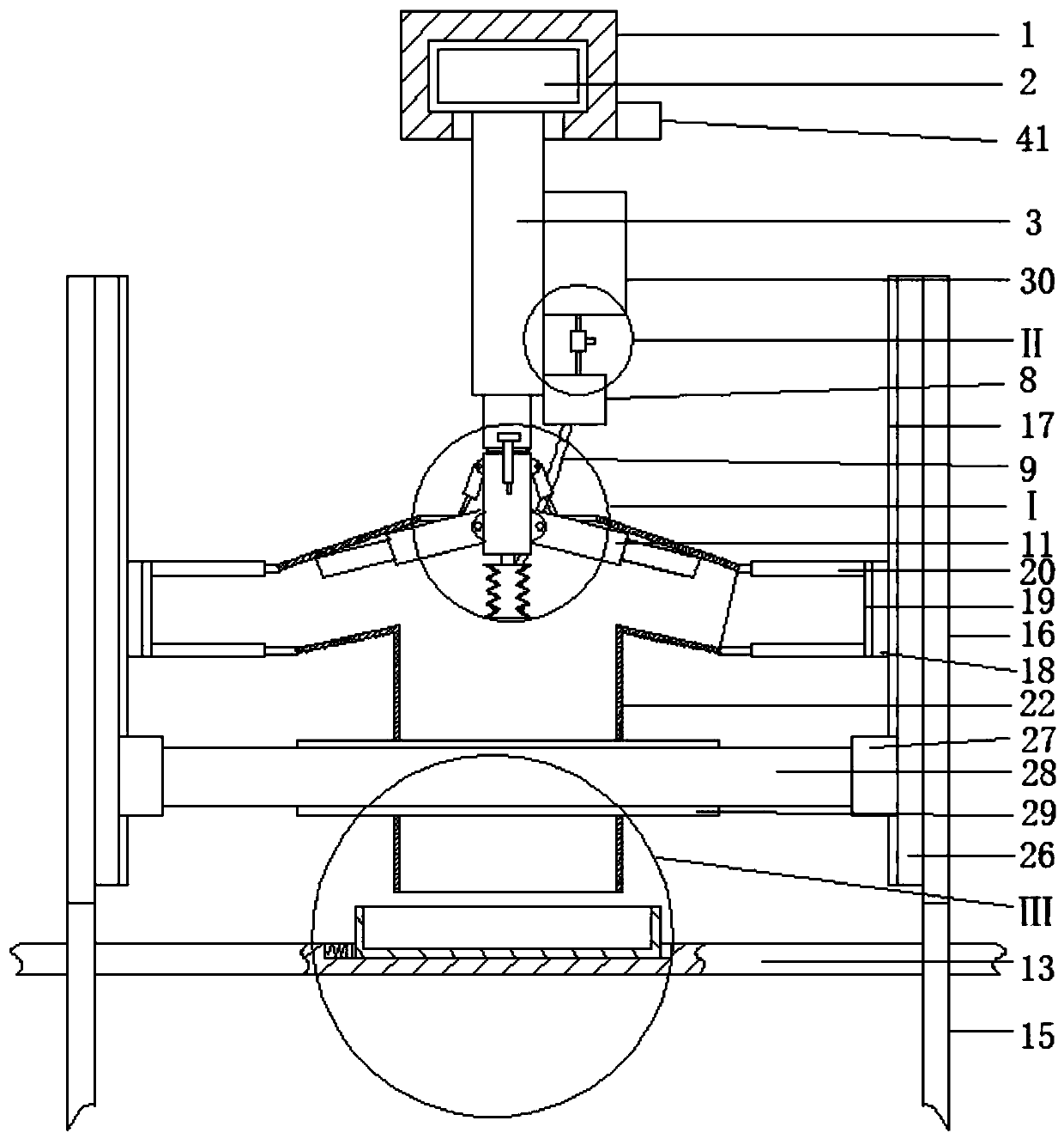
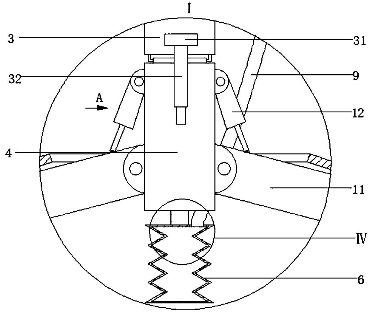
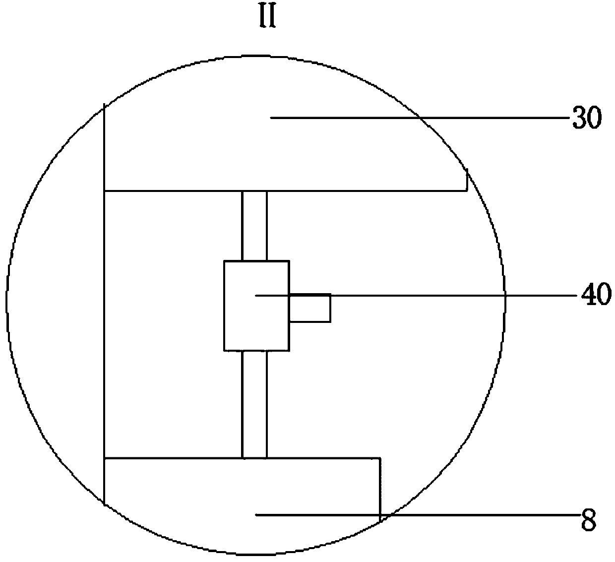
[0018]A new type of conveying equipment for garment production, as shown in the figure, includes an electric slide rail 1 of a suspended conveying device, and several first sliders 2 are installed in the electric slide rail 1, and the bottom of the first slider 2 is fixed and movable The rod faces down the first electric telescopic rod 3, the lowe...


PUM


Abstract

Novel conveying equipment for garment production comprises an electric sliding rail of a hanging type conveyer. A plurality of first sliders are installed in the electric sliding rail in a matched mode. First electric telescopic rods with downward movable rods are fixedly installed at the bottoms of the first sliders correspondingly. Vertical plates are hinged to the lower ends of the movable rodsof the first electric telescopic rods. Rectangular blocks are fixedly installed on the front side walls of the movable rods of the first electric telescopic rods. Fifth electric telescopic rods are arranged on the lower sides of the rectangular blocks. Elastic telescopic pipes with closed upper and lower end openings are fixedly installed at the bottoms of the vertical plates through connection rods. Through a reasonable structure, garment sizing, garment dedusting, garment ironing, garment folding, packaging and other series of automatic processing procedures are achieved, a garment production line is shortened, thus the needed plant area and garment production time are reduced, the garment processing process is more automatic, the phenomenon of too many unqualified garment products caused by errors of manual garment treatment is avoided, and garment production quality is improved.

Description

technical field [0001] The invention belongs to the field of conveying equipment for garment production, in particular to a novel conveying equipment for garment production. Background technique [0002] After the garment is sewn, the residual thread and plush on the surface need to be removed and then ironed and packaged. With the development of economy and technology, the production of garments has become more and more automated, and the garments are often sent to the next through the conveyor line. One-step processing, because the hanging conveyor line has the advantages of small space occupation, labor saving and high work efficiency, the existing garment production process usually uses the hanging conveyor line for clothing transmission, but because the hanging conveyor in the prior art The line usually uses hooks to fix the clothes, which makes the clothes easily deformed, and the hanging conveyor line only plays the role of transmission, and cannot cooperate with a se...

Claims


Application Information

Patent Timeline
Patent Type & Authority Applications(China)
IPC IPC(8): B65G35/00B65B63/04B65B25/20B65B35/10D06B1/02D06B23/04D06F89/02D06G1/00
CPCB65B25/20B65B35/10B65B63/04B65G35/00B65G2201/0229D06B1/02D06B23/04D06F89/02D06G1/00
Inventor 陈力
Owner 潜江东颢制衣有限公司
Why Eureka
Try Eureka