All-metal double-row tapered gate high-frequency structure

A high-frequency structure and all-metal technology, which is applied in the field of all-metal double-row gradient gate high-frequency structures, can solve the problems of terahertz traveling wave tubes, such as difficult output power and interaction efficiency, insufficient coupling impedance, and large transmission loss. Achieve the effects of large coupling impedance, small transmission loss, and wide operating bandwidth

Inactive Publication Date: 2020-05-08
UNIV OF ELECTRONICS SCI & TECH OF CHINA
View PDF9 Cites 8 Cited by
  • Summary
  • Abstract
  • Description
  • Claims
  • Application Information

AI Technical Summary

Problems solved by technology

However, this stepped rectangular interleaved double-gate high-frequency structure has poor transmission (that is, large transmission loss) and the coupling impedance is not high enough, which means that it is difficult for a THz TWT to have high output power and interaction efficiency.

Method used


Image

  • All-metal double-row tapered gate high-frequency structure
  • All-metal double-row tapered gate high-frequency structure
  • All-metal double-row tapered gate high-frequency structure

Examples


Embodiment 1

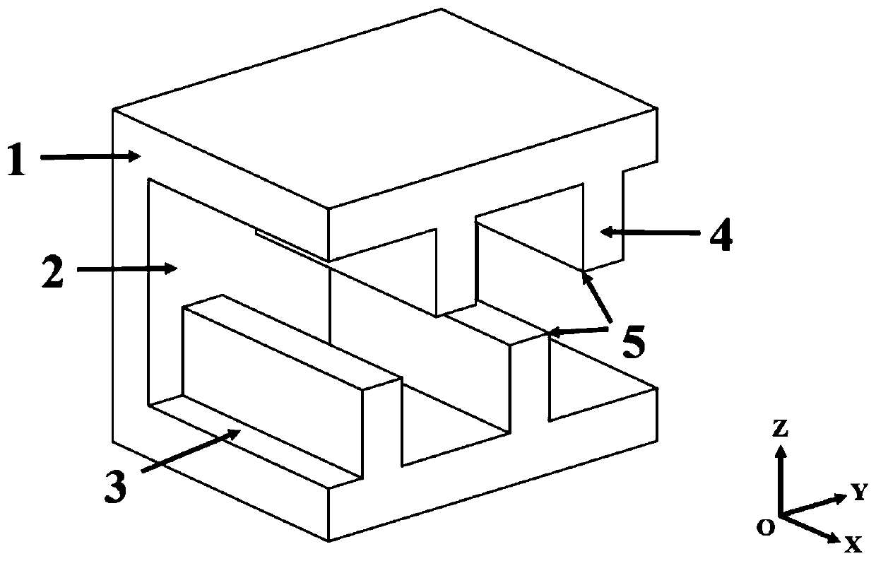
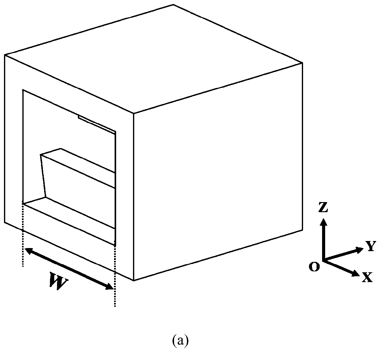
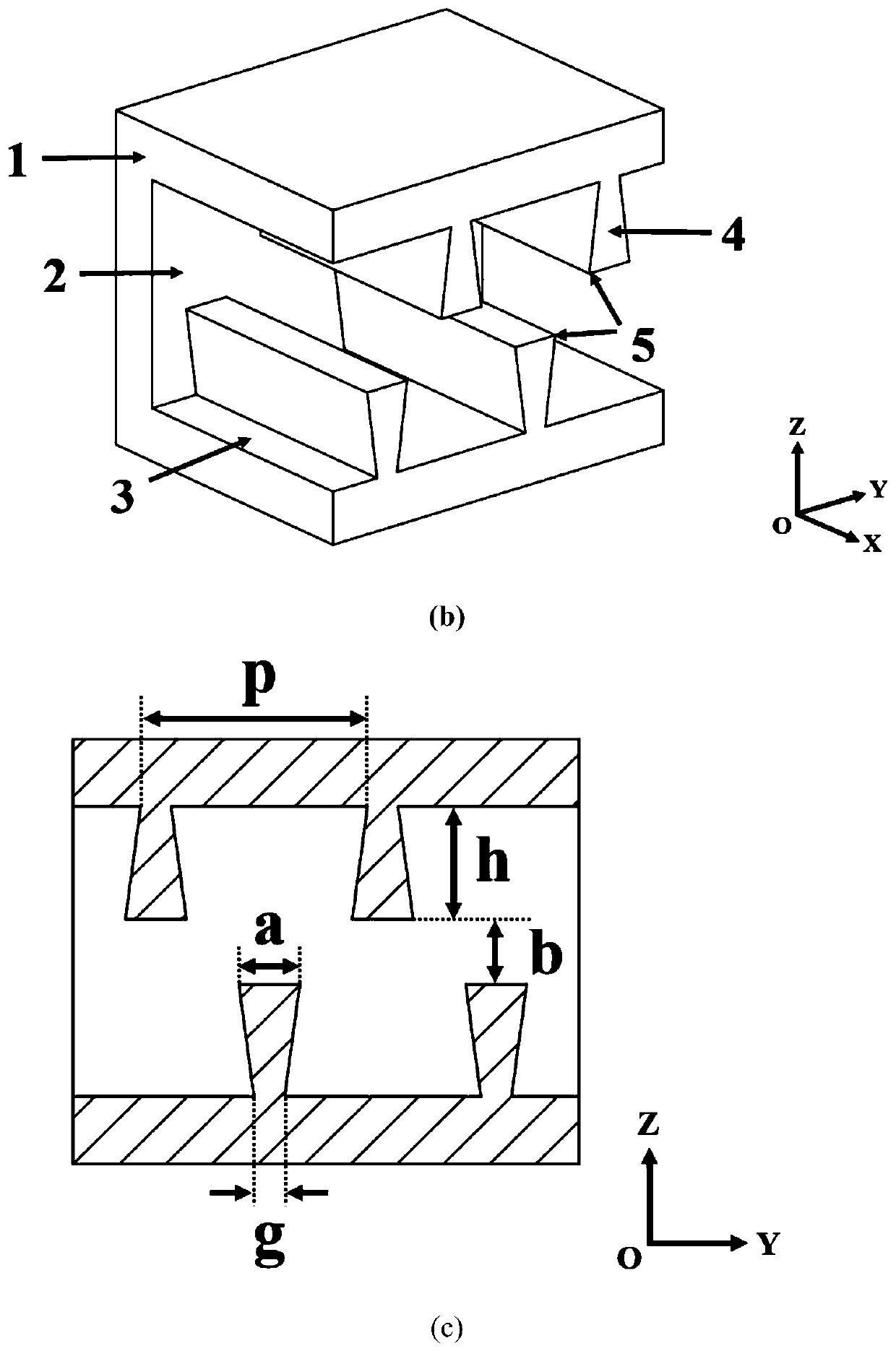
[0028] An all-metal double-row gradient gate high-frequency structure, such as figure 2 As shown, it includes a rectangular waveguide 1. The rectangular waveguide includes a wide side 3 and a narrow side 2, and grating teeth 4 arranged periodically on the inner walls of the upper and lower wide sides of the rectangular waveguide. For half a period p / 2, the vertical section of the grid teeth is an isosceles trapezoid, and the lower base of the isosceles trapezoid is set on the side close to the electron injection channel, so that the bottom angle 5 of the grid is an acute angle.

[0029] When the high-frequency structure described in this embodiment works in the frequency range of 210GHz to 230GHz, its structural size parameters are as follows: w=0.78mm, b=0.15mm, h=0.26mm, p=0.52mm, g=0.07mm, a= 0.14mm. The high-frequency structure material selected in the simulation calculation is high-conductivity oxygen-free copper.

[0030] The high-frequency characteristics and transmi...

Embodiment 2

[0032] An all-metal double-row gradient gate high-frequency structure, such as image 3As shown, it includes a rectangular waveguide 1. The rectangular waveguide includes a wide side 3 and a narrow side 2, and grating teeth 4 arranged periodically on the inner walls of the upper and lower wide sides of the rectangular waveguide. For half a period p / 2, the vertical section of the grid teeth is in the shape of a biconcave lens, the upper base and the lower base of the biconcave lens are equal, the lower base is set on the side close to the electron injection channel, and the upper and lower bases The radius of curvature of the connecting sides of the sides is r, so that the bottom corner 5 of the grid is an acute angle.

[0033] When the high-frequency structure described in this embodiment works in the frequency range of 210GHz to 230GHz, its structural size parameters are as follows: w=0.78mm, b=0.15mm, h=0.26mm, p=0.52mm, r=0.198mm, a= 0.14mm. The high-frequency structure m...


PUM


Abstract

The invention provides an all-metal double-row tapered gate high-frequency structure, belongs to the field of vacuum electronic devices, and is suitable for millimeter waves and terahertz frequency bands. According to the structure, the shape of the grid teeth is innovatively designed, so that the grid bottom angle of the cross section of each grid tooth is an acute angle; compared with a conventional rectangular staggered double-grid structure, the high-frequency structure has higher coupling impedance at 210 GHz to 230 GHz, which means that a slow wave structure has higher interaction efficiency; the phase velocity is lower, which indicates that the travelling wave tube adopting the novel all-metal double-row tapered gate high-frequency structure can work at lower voltage; the S21 absolute value of the high-frequency structure is smaller, the transmission loss is smaller, and the high-frequency structure is of great significance to the development of millimeter wave and terahertz vacuum electronic devices.

Description

technical field [0001] The invention belongs to the field of vacuum electronic devices, and in particular relates to an all-metal double-row gradient gate high-frequency structure, which works in millimeter wave and terahertz frequency bands. Background technique [0002] In recent years, with the development of millimeter wave and terahertz technology, research on millimeter wave and terahertz sources has become one of the current international hot spots, and this research is also the fifth generation mobile communication technology (5G) and even the sixth generation mobile communication technology ( 6G) is the basis for rapid development. Common millimeter-wave and terahertz sources include solid-state electronic devices and vacuum electronic devices. Compared with solid-state electronic devices, vacuum electronic devices have the advantages of high power, high efficiency, high gain and wide operating bandwidth. Among the numerous vacuum electronic devices, the traveling...

Claims


Application Information

Patent Timeline
Patent Type & Authority Applications(China)
IPC IPC(8): H01J23/24H01J25/34
CPCH01J23/24H01J25/34
Inventor 段兆云江胜坤唐涛王战亮巩华荣宫玉彬
Owner UNIV OF ELECTRONICS SCI & TECH OF CHINA
Why Eureka
Try Eureka