
Vertical power device and barrier modulation method thereof

A technology for power devices and manufacturing methods, applied in semiconductor/solid-state device manufacturing, semiconductor devices, electrical components, etc., can solve problems such as difficulties, improve blocking ability and reliability, improve blocking ability and reliability, reduce The effect of craft difficulty

Inactive Publication Date: 2020-05-08
ZHEJIANG UNIV
View PDF9 Cites 0 Cited by
  • Summary
  • Abstract
  • Description
  • Claims
  • Application Information

AI Technical Summary

Problems solved by technology

However, due to the fundamental limitations of local P-type ion implantation and activation efficiency, it is extremely difficult to achieve local P-type doping of III-V nitrides by thermal diffusion and ion implantation, which makes it possible to obtain efficient and stable P in III-V nitrides. Challenging structure

Method used

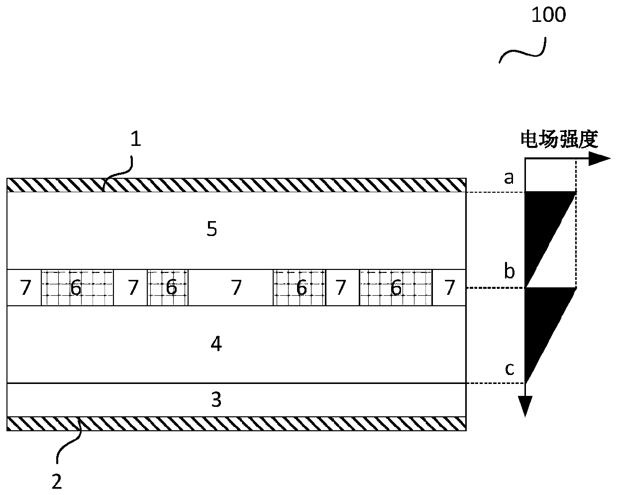
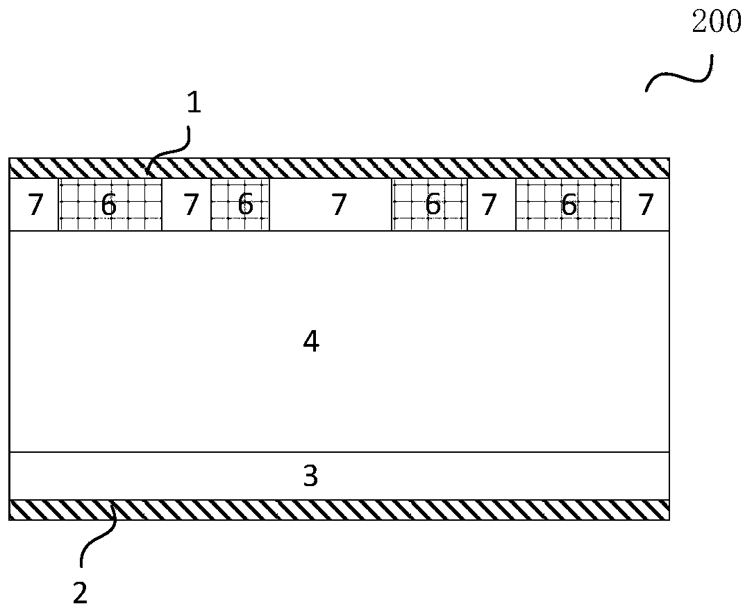
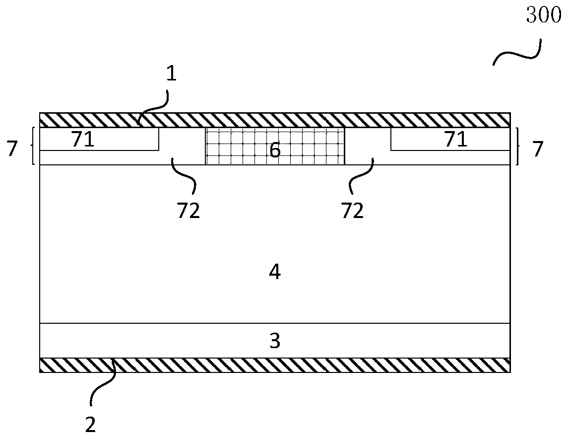

Image

  • Vertical power device and barrier modulation method thereof
  • Vertical power device and barrier modulation method thereof
  • Vertical power device and barrier modulation method thereof

Examples


Embodiment Construction

[0019] Specific embodiments of the present invention will be described in detail below in conjunction with the accompanying drawings. It should be noted that the embodiments described here are only for illustration, not for limiting the present invention. In the following description, numerous specific details are set forth in order to provide a thorough understanding of the present invention. However, it will be understood by one of ordinary skill in the art that these specific details are not required to practice the present invention. Additionally, in some embodiments, well-known circuits, materials or methods have not been described in detail in order not to obscure the present invention.

[0020] Throughout this specification, reference to "one embodiment," "an embodiment," "an example," or "example" means that a particular feature, structure, or characteristic described in connection with the embodiment or example is included in the present invention. In at least one em...


PUM


Abstract

Disclosed is an III-V group nitride power device. The III-V group nitride power device comprises an anode, a cathode and a substrate, and the III-V group nitride power device comprises an N-type gallium nitride drift region located above the substrate, and P-type-like regions and space charge windows are alternately arranged. The P-type-like regions are formed in the N-type gallium nitride drift region and located under the anode, electronegative ions are introduced into the P-type-like regions, the space charge windows are located between every two adjacent P-type-like regions, and a currentpath is provided between the anode and the cathode, wherein the P-like region and the space charge window are located in the N-type gallium nitride drift region or located on the surface of the III-Vgroup nitride power device. According to the structure, the forward conduction performance, the reverse breakdown performance and the reverse leakage current performance of the device can be considered at the same time, the feasibility of the technology for achieving the structure is high under the conditions of laboratories and industrial production, and the method is simple.

Description

technical field [0001] The invention relates to a semiconductor device, in particular to a III-V group nitride power device. Background technique [0002] Compared with the first-generation semiconductors represented by silicon and the second-generation semiconductors represented by gallium arsenide, the third-generation semiconductors represented by silicon carbide and III-V nitrides have a large band gap, The characteristics of high critical breakdown field strength and high electron saturation rate have significant advantages in power electronics applications. [0003] After the P-type semiconductor and the N-type semiconductor are in contact, a PN junction will be formed, and the P-type and N-type semiconductors near the interface will deplete each other to form a space charge region, and the thickness of the space charge region will change with the change of the applied electric field. Change. In a critical situation, the P-type and N-type semiconductors will be compl...

Claims


Application Information

Patent Timeline
Patent Type & Authority Applications(China)
IPC IPC(8): H01L29/06H01L29/20H01L21/329H01L29/872
CPCH01L29/0684H01L29/2003H01L29/66143H01L29/872
Inventor 杨树刘宇鑫盛况
Owner ZHEJIANG UNIV
Learn More