A Self-inspection System for On-Plate Seismic Wave Fuze

A self-inspection system and seismic wave technology, applied in geophysical measurement, instruments, etc., can solve the problems of self-inspection system hardware system complexity, inflexibility, human judgment, etc., and achieve huge engineering application value and theoretical guidance significance, self-inspection system Simplicity and the effect of reducing consumables

Active Publication Date: 2021-04-20
NAVAL UNIV OF ENG PLA
View PDF8 Cites 0 Cited by
  • Summary
  • Abstract
  • Description
  • Claims
  • Application Information

AI Technical Summary

Problems solved by technology

[0006] (1) Special self-inspection equipment is required to pass through the external interface of the system and follow certain self-inspection steps, which often requires a lot of manpower and material resources
[0007] (2) The self-inspection steps are cumbersome and single, inflexible, and one-step mistakes make mistakes in all
[0008] (3) The quality of self-inspection is not high, only the internal software can be debugged, and there is no self-inspection of the hardware integrity of the detection system
[0009] (4) The software of the self-inspection system is complicated, and it takes a long time to complete the whole set of self-inspection, which is not convenient for the rapid self-inspection of the magnetic detection system
[0010] (5) The self-inspection results are not easy to distinguish. The existing self-inspection equipment lacks the ability to display the self-inspection results. There are only a few indicators to output the results. The self-inspection results need human judgment and are prone to errors
[0011] (6) The hardware system of the self-inspection system is complex and difficult to maintain
[0013] (1) How to design a self-inspection system that can be integrated into the fuze system needs to solve the compatibility problem between the fuze system and the self-inspection system

Method used

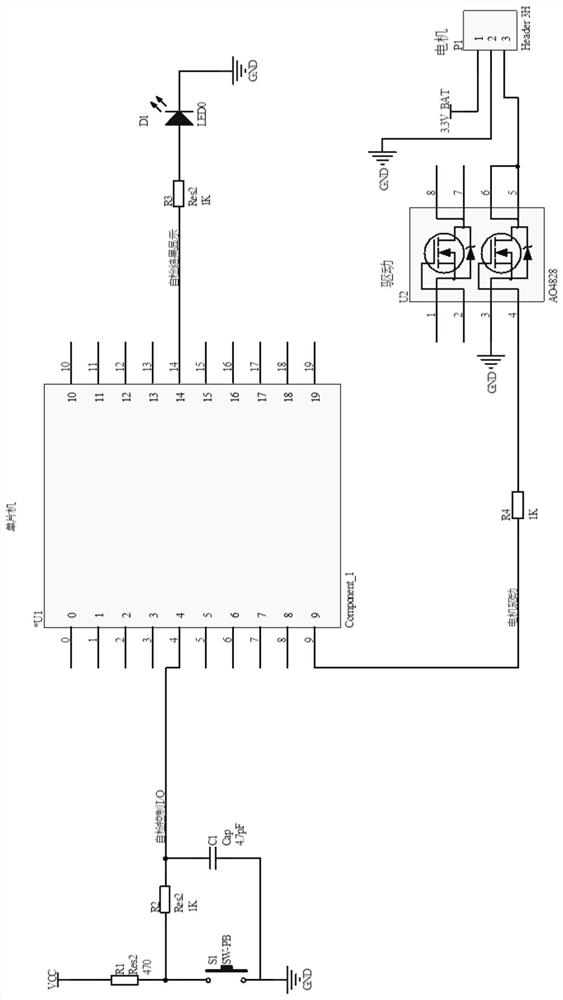

Image

  • A Self-inspection System for On-Plate Seismic Wave Fuze
  • A Self-inspection System for On-Plate Seismic Wave Fuze
  • A Self-inspection System for On-Plate Seismic Wave Fuze

Examples


Embodiment 1

[0137] 1.1 Principle of self-testing of on-plate seismic wave fuze

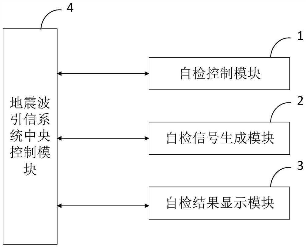
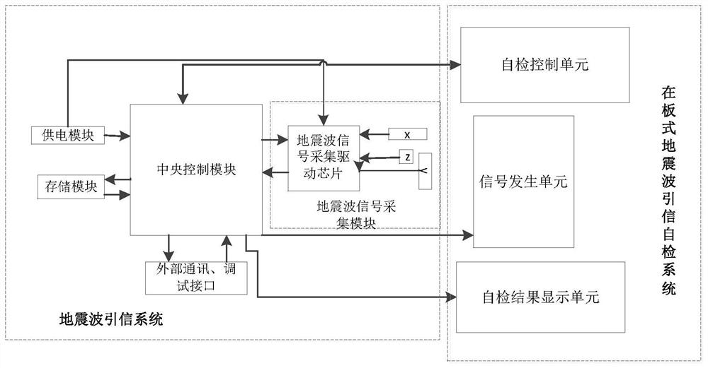
[0138] The main working principle of the plate seismic wave fuze self-inspection system is: the seismic wave fuze system itself generates a specific seismic wave signal, and the self-inspection signal is collected through the signal acquisition module of the fuze itself, and then the collected signal is judged, and according to The results of the evaluation further judge whether the function of the seismic wave fuze is complete. Its biggest feature is that the self-test is integrated into the fuze system, and the additional self-test equipment of the fuze is omitted.

[0139] Such as figure 2 Shown is the functional block diagram of the on-board magnetic module self-test system. It mainly includes a self-inspection control unit, a self-inspection signal generation unit, and a self-inspection result display unit.

[0140] The self-test control unit is the circuit that controls the fuze system to start the ...


PUM


Abstract

The invention belongs to the technical field of seismic wave fuze design, and discloses a self-inspection system and method for a plate-type seismic wave fuze. The self-inspection control module is used to control the fuze system to start the self-inspection program, and controls the central control model of the fuze system to generate a certain self-inspection control. signal; the self-inspection signal generation module is used to receive the self-inspection control signal output by the central control module of the fuze system, and generates a corresponding identifiable seismic wave signal; the self-inspection result display module is used to display the self-inspection result in a certain way. The self-inspection system of the present invention is directly integrated into the seismic wave fuze system, and the existing hardware resources are fully utilized to complete the self-inspection; the self-inspection system is simple and easy to implement; the self-inspection method is simple and easy to operate; the self-inspection steps are simple and time-consuming ; The system structure is simple, easy to manufacture and maintain; low power consumption, and has good battery life. The self-checking method of the seismic wave fuze system of the invention has huge engineering application value and theoretical guiding significance.

Description

technical field [0001] The invention belongs to the technical field of seismic wave fuze design, and in particular relates to a self-inspection system for a plate type seismic wave fuze. Background technique [0002] At present, the existing technologies commonly used in the industry are as follows: [0003] Undersea mines are underwater weapons used to attack submarines and surface ships. Because it is arranged on the bottom of the sea, it is not easy to be swept away by modern mine-sweeping equipment, and the attack time on the target is short, so that the enemy cannot take countermeasures and implement evasive motives, so it can effectively attack submarines and various surface ships. However, with the development of mine-sweeping technology With the development, the detection equipment and mine-sweeping devices of submarines and surface ships are becoming more and more advanced, and the fuze technology of submarine mines also needs to be improved and updated. At presen...

Claims


Application Information

Patent Timeline
Patent Type & Authority Patents(China)
IPC IPC(8): G01V13/00
CPCG01V13/00
Inventor 周穗华戴忠华单珊
Owner NAVAL UNIV OF ENG PLA
Why Eureka
Try Eureka