Tubing and sucker rod identification and tracking system

An identification and tracking system technology, applied in electromagnetic radiation induction, instruments, induction recording carriers, etc., can solve the problems of high labor and material resources, inability to accurately judge, difficult to accurately count oil pipes or sucker rods, etc., to ensure the success rate. , Increase the probability of successful identification, and avoid the effect of weakening the strength

Active Publication Date: 2020-09-25
正弦科技有限公司
View PDF10 Cites 3 Cited by
  • Summary
  • Abstract
  • Description
  • Claims
  • Application Information

AI Technical Summary

Problems solved by technology

In the prior art, the inspection method of pulling all the oil pipes and sucker rods back to the inspection station for flaw detection is mostly used to realize the inspection. This method has two defects: on the one hand, it consumes a lot of manpower and material resources; on the other hand, it is difficult to inspect each It is impossible to make full use of each tubing and sucker rod, and it is impossible to accurately judge the problems existing in the downhole according to the damage status
However, in actual use, it is found that there are the following problems in the implementation of this method: to realize the reading of the chip, a communication connection must be established with the chip, and how to set the communication mode, how to ensure the effectiveness of chip identification, and how to reduce the hardware of the communication system Cost, how to set up the chip identification device in the narrow annular space between the casing and the oil pipe, etc., this series of problems must be solved through a lot of creative labor

Method used


Image

  • Tubing and sucker rod identification and tracking system
  • Tubing and sucker rod identification and tracking system
  • Tubing and sucker rod identification and tracking system

Examples


Embodiment Construction

[0031] The present invention will be further described below in conjunction with accompanying drawing:

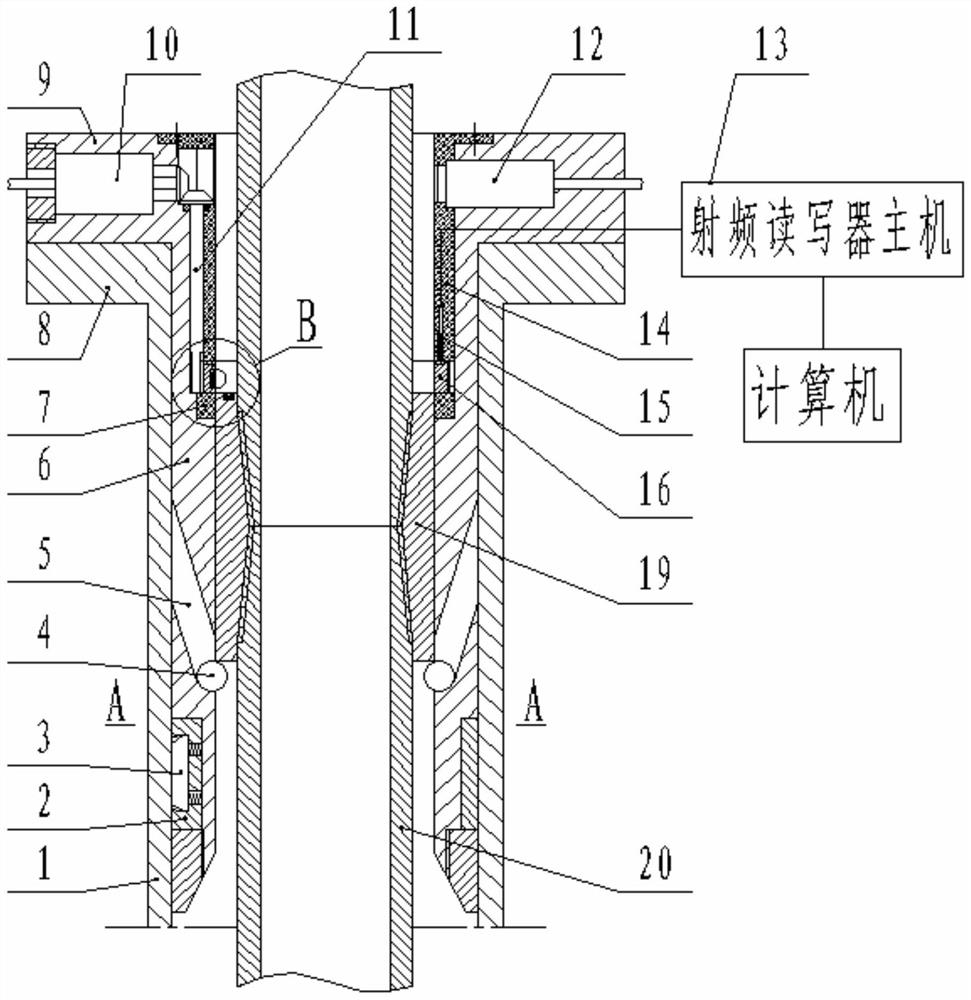
[0032] Such as figure 1 As shown, the present invention includes a detection probe 12, a chip, a chip reading device and a collar 19. The above are existing structures in the prior art and will not be repeated here.

[0033] The detection probe 12 is installed on an installation cylinder 6 independent of the wellhead, and the chip is installed on the upper end surface of the collar 19 . By adopting this structure, the original wellhead does not need to be modified when the present invention is installed, and the installation is more convenient. In addition, the present invention arranges the chip on the upper end surface of the oil pipe coupling or the sucker rod coupling (collectively referred to as "coupling 19") instead of on the oil pipe or sucker rod. The use has an impact, and it also avoids weakening the strength of the oil pipe or sucker rod by installing chips. ...


PUM


Abstract

An oil pipe and sucker rod identity recognition tracking system relates to the technical field of oil field downhole tools and comprises a detection probe, a chip, a chip reading device and a coupling, wherein the detection probe is mounted on a mounting cylinder independent of a wellhead; the chip is mounted on the upper end face of the coupling; the chip is a radio frequency electronic tag; thechip reading device is a radio frequency reader-writer; the structure of the radio frequency reader-writer comprises a radio frequency reader-writer host and a radio frequency antenna; the radio frequency antenna is connected with the radio frequency reader-writer host through a wire; the radio frequency antenna is arranged on the inner side of the mounting cylinder; and the radio frequency antenna is connected with the radio frequency reader-writer host through a wire. The chip is arranged on the upper end face of the oil pipe coupling or the sucker rod coupling (collectively called coupling)instead of the oil pipe or the sucker rod, the installation mode cannot affect use of the coupling, and meanwhile weakening of the strength of the oil pipe or the sucker rod due to installation of the chip is avoided.

Description

technical field [0001] The invention belongs to the technical field of oilfield downhole tools, in particular to an identification and tracking system for oil pipes and sucker rods. Background technique [0002] In the pumping unit oil production system, the oil pipe and sucker rod in the oil well will leak or break due to cracks, holes, corrosion, and wear. Once this happens, it will cause large economic losses to the oil field. Therefore, Effective management of tubing and sucker rod damage is essential. In the prior art, the inspection method of pulling all the oil pipes and sucker rods back to the inspection station for flaw detection is mostly used to realize the inspection. This method has two defects: on the one hand, it consumes a lot of manpower and material resources; on the other hand, it is difficult to inspect each It is impossible to make full use of each tubing or sucker rod, and it is impossible to accurately judge the problems existing in the downhole accor...

Claims


Application Information

Patent Timeline
Patent Type & Authority Patents(China)
IPC IPC(8): G06K7/10
CPCG06K7/10316
Inventor 席小平徐国民任成锋高恒达付尧李欣宇任立新梁猛张学斌崔金哲李季公杰
Owner 正弦科技有限公司
Why Eureka
Try Eureka