
Factory electric energy management and control system and method based on side-cloud cooperation

A power management and factory technology, applied in the direction of comprehensive factory control, general control system, control/regulation system, etc., can solve problems such as inability to realize joint control, insufficient power supply, and excess power supply

Pending Publication Date: 2020-05-12
CHONGQING UNIV OF POSTS & TELECOMM
View PDF10 Cites 6 Cited by
  • Summary
  • Abstract
  • Description
  • Claims
  • Application Information

AI Technical Summary

Problems solved by technology

[0006] ①Insufficient real-time performance: The power data information on the factory site is huge. Moving all the power data to the cloud for centralized calculation will cause delays in the transmission of control commands and increase electricity costs.
[0007] ② Power supply - power consumption cannot be jointly controlled: the factory power consumption layer and the factory power supply layer cannot achieve joint control, resulting in insufficient or excess power supply, resulting in increased electricity costs
[0008] ③ Insufficient security: As a centralized computing center, the factory cloud plays a role in centralized scheduling of the entire factory power management and control system. Once faced with security threats, the consequences are extremely serious

Method used


Image

  • Factory electric energy management and control system and method based on side-cloud cooperation
  • Factory electric energy management and control system and method based on side-cloud cooperation
  • Factory electric energy management and control system and method based on side-cloud cooperation

Examples


Embodiment Construction

[0075] The following describes the implementation of the present invention through specific specific examples. Those skilled in the art can easily understand other advantages and effects of the present invention from the content disclosed in this specification. The present invention can also be implemented or applied through other different specific embodiments, and various details in this specification can also be modified or changed based on different viewpoints and applications without departing from the spirit of the present invention. It should be noted that the illustrations provided in the following embodiments are only illustrative to illustrate the basic concept of the present invention. In the case of no conflict, the following embodiments and features in the embodiments can be combined with each other.

[0076] Among them, the drawings are only used for exemplary description, and they are only schematic diagrams rather than physical drawings, and cannot be understood as...


PUM


Abstract

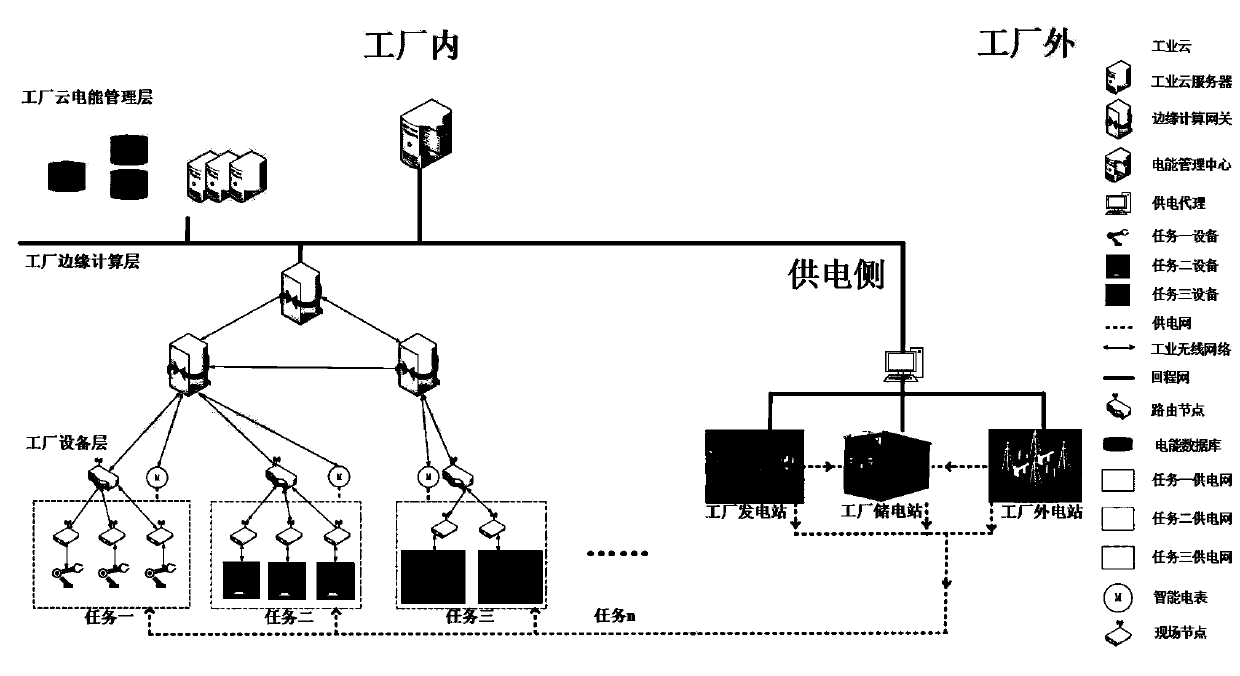
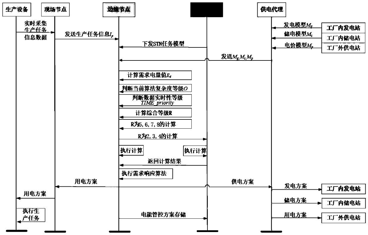
The invention relates to a factory electric energy management and control system based on side-cloud cooperation. The system comprises a cloud electric energy management layer, an edge calculation layer, an equipment layer and a power supply side. The invention provides a factory electric energy management and control method based on side cloud cooperation. The method comprises the following steps: 1) forming an industrial field network by field nodes, routing nodes and equipment for executing production tasks in an equipment layer; 2) analyzing and sending production task information data; 3)issuing the STN model of the production field to an edge node; 4) enabling the power supply agent to send the power generation model, the power storage model and the electricity price model to edge nodes; 5) enabling the edge nodes to calculate the electric quantity required for completing the production task; (6) calculating a comprehensive grade value; (7) executing a high grade by an edge nodeand executing a low grade by a cloud electric energy management center, (8) executing a demand response algorithm by the edge node, (9) executing a production task by production equipment according to a calculation result, and executing corresponding schemes by a factory power station, a power storage station and a factory external power supply station according to results.

Description

Technical field [0001] The invention belongs to the field of factory power management and control, and relates to a factory power management and control system and method based on edge-cloud collaboration. Background technique [0002] Edge computing is a distributed and open platform that integrates core capabilities of network, computing, storage, and applications on the edge of the network close to the source of things or data. It provides edge intelligent services nearby to meet the needs of industry digitalization in agile connection, real-time business, data optimization, and application. Key requirements for intelligence, security, and privacy protection. It can be used as a bridge connecting the physical and digital worlds, enabling smart assets, smart gateways, smart systems, and smart services. Because the edge side needs to support multiple network interfaces, protocols and topologies, real-time business processing and deterministic delay, data processing and analysis...

Claims


Application Information

Patent Timeline
IPC IPC(8): G06Q10/06G06Q50/06H04L29/08G16Y10/35G16Y40/10G16Y40/35G16Y40/20
CPCG06Q10/06313G06Q10/06315G06Q50/06H04L67/10G06F1/26G06F1/28G06F1/3296Y02P90/02G06Q10/0633G05B19/41885G06F1/329G06F9/505G06F9/5072G06F9/5088G06F1/3203
Inventor 王平杨旭魏旻李彩芹
Owner CHONGQING UNIV OF POSTS & TELECOMM
Learn More