
Mixing and stirring equipment for detecting polluted phenolic compounds

A phenolic compound, mixing and stirring technology, applied in the field of pollutant detection, to achieve the effect of improving liquid fluidity, improving accuracy, and shortening detection time

Inactive Publication Date: 2020-05-15
孙丽
View PDF0 Cites 0 Cited by
  • Summary
  • Abstract
  • Description
  • Claims
  • Application Information

AI Technical Summary

Problems solved by technology

[0003] In the detection process of pollutant phenolic compounds, it is necessary to drip the reagent into the waste water and mix with the waste water therein. Therefore, mixing and stirring equipment is required, and the existing mixing and stirring equipment has a simple structure, especially for the lack of mixing in the vertical direction. Therefore need to design a kind of mixing and stirring equipment to solve the above problems

Method used


Image

  • Mixing and stirring equipment for detecting polluted phenolic compounds
  • Mixing and stirring equipment for detecting polluted phenolic compounds
  • Mixing and stirring equipment for detecting polluted phenolic compounds

Examples


Embodiment 1

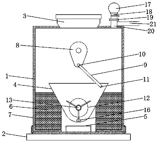
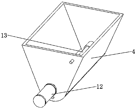
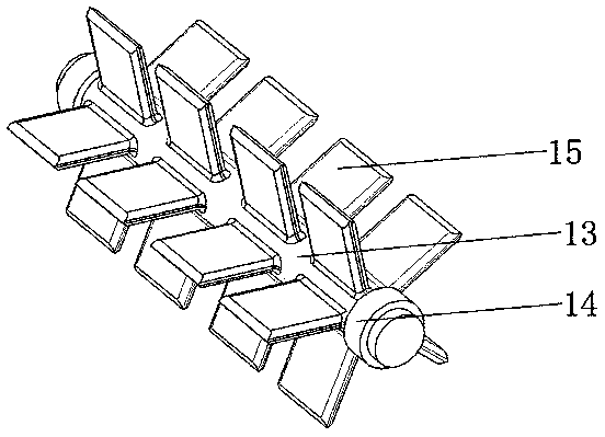
[0023] Please refer to the figure, in an embodiment of the present invention, a mixing and stirring device for the detection of polluted phenolic compounds includes a housing 1, a base 2, a feed hopper 3, a mixing bin 4 and a collection box 5; the base 2 is fixedly installed on On the bottom of the shell 1, the feed hopper 3 is arranged on the top of the shell 1 and communicates with the inside of the shell 1. The feed hopper 3 is covered with a sealing cover to keep the internal seal when stirring and mixing; The middle part is provided with a mixing chamber 4 horizontally located directly below the feeding hopper 3, the liquid falling in the feeding hopper 3 directly enters the mixing chamber 4, the opening of the mixing chamber 4 faces upwards and the width of the upper port is greater than the width of the bottom, which is convenient The liquid falls into it, and the bottom of the mixing chamber 4 is set as a horizontal arc structure, which is convenient for stirring and mi...

Embodiment 2

[0027] On the basis of embodiment 1, the top of the housing 1 is communicated with an exhaust pipe 20, the top of the exhaust pipe 20 is provided with a connecting flange 19, and the sampling pipe 18 is detachably connected to the connecting flange 19, A sampling airbag 17 is installed on the top of the sampling pipe 18, so that the gas generated during the internal reaction enters into the sampling airbag 17 for collection, and a valve is installed on the sampling pipe 18, and the sampling pipe 18 can be removed from the exhaust pipe by closing the valve after sampling. 20, and the exhaust pipe 20 is also communicated with an exhaust pipe 21 through a tee, so that excess gas is discharged from the shell 1.

[0028]When mixing, the sewage is sent from the feed hopper 3 to the mixing chamber 4 in the shell 1, and then the reagent is added to the inside of the mixing chamber 4, the feed hopper 3 is sealed, and the driving motor of the cam 8 is started to make The cam 8 rotates, ...


PUM


Abstract

The invention relates to the field of pollutant detection, and particularly discloses mixing and stirring equipment for detecting polluted phenolic compounds, which comprises a shell, a base, a feeding hopper, a mixing bin and a collecting box. The mixing bin horizontally located under the feeding hopper is arranged in the middle in the shell. The bottom of the mixing bin is arranged to be of a horizontal arc-shaped structure, a horizontal transmission shaft is arranged on a center shaft of the bottom arc-shaped structure of the mixing bin in a penetrating mode, a connecting rod swinging in the vertical direction is rotationally connected to a second pin shaft, and a cam rotating in the vertical direction is rotationally connected to the upper end of the connecting rod through an installedfirst pin shaft. A plurality of stirring blades are fixedly arranged on the corresponding side wall of the transmission shaft in the mixing bin. The cam drives the mixing bin to shake left and right,sufficient shaking of the mixing bin is guaranteed through supporting buffer blocks arranged on the two sides, and the liquidity of liquid in the mixing bin is improved. Meanwhile, a stirring motor drives the stirring blades to stir the shaking mixing bin, so that internal sewage and chemicals are rapidly mixed.

Description

technical field [0001] The invention relates to the field of pollutant detection, in particular to a mixing and stirring device for detecting polluting phenolic compounds. Background technique [0002] Phenol pollution in the environment mainly refers to the pollution of water by phenolic compounds. Phenol-containing wastewater is one of the most harmful and widely polluting industrial wastewater in the world today, and is an important source of water pollution in the environment. Phenol is contained in the wastewater discharged from many industrial fields such as gas, coking, oil refining, metallurgy, machinery manufacturing, glass, petrochemical, wood fiber, chemical organic synthesis industry, plastic, medicine, pesticide, paint and other industries. If the waste water is not treated, it can pollute air, water, soil and food if it is directly discharged and irrigated farmland. [0003] In the detection process of pollutant phenolic compounds, it is necessary to drip the ...

Claims


Application Information

Patent Timeline
Patent Type & Authority Applications(China)
IPC IPC(8): B01F11/00G01N1/22G01N1/38G01N31/00
CPCG01N31/00G01N1/2226G01N1/38G01N2001/2229B01F31/00
Inventor 孙丽
Owner 孙丽
Learn More