
Transferring mechanism of plastic particle storage bag

A transfer mechanism and plastic granule technology, applied in the direction of hoisting device, lifting frame, etc., can solve the problems of high labor intensity, unsatisfactory production and use, and low degree of automation of production and processing, and achieve reasonable structural design, high efficiency and smooth horizontal reciprocating translational movement Effect

Active Publication Date: 2020-05-15
桐乡市建春塑业股份有限公司
View PDF13 Cites 0 Cited by
  • Summary
  • Abstract
  • Description
  • Claims
  • Application Information

AI Technical Summary

Problems solved by technology

In the production and processing process of plastic pipes, synthetic resin is used as the main raw material, stabilizers, lubricants and plasticizers are added, and various raw materials are fully stirred and mixed, then melted and processed, and extruded in the pipe making machine , the main raw material for the production and processing of plastic pipes, synthetic resin, exists in the form of granules. The synthetic resin is mainly stored and packaged in plastic woven bags. During the production and processing of plastic pipes, the bagged synthetic resin needs to be fed into the mixing tank In China, the existing synthetic resin feeding method is mainly carried out manually. During the operation, a single person or two persons are used to transport the bagged synthetic resin to the top of the mixing tank, so that the synthetic resin particles in the plastic woven bag can be discharged. To the mixing tank, the transfer of the existing plastic particle storage bags is mainly realized by manual handling, the labor intensity of the workers is relatively high, and it is difficult for the workers to smoothly and efficiently transport the plastic particle storage bags to the top of the mixing tank for unloading, and the production and processing are automated The degree is low, it is difficult to realize the continuous large-scale production and processing of plastic pipes, and it cannot meet the needs of production and use

Method used


Image

  • Transferring mechanism of plastic particle storage bag
  • Transferring mechanism of plastic particle storage bag
  • Transferring mechanism of plastic particle storage bag

Examples


Embodiment Construction

[0016] In order to further describe the present invention, the specific implementation of a plastic particle storage bag transfer mechanism will be further described below in conjunction with the accompanying drawings. The following examples are explanations of the present invention and the present invention is not limited to the following examples.

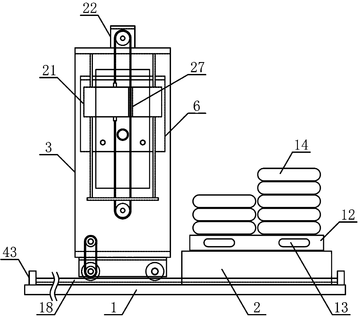
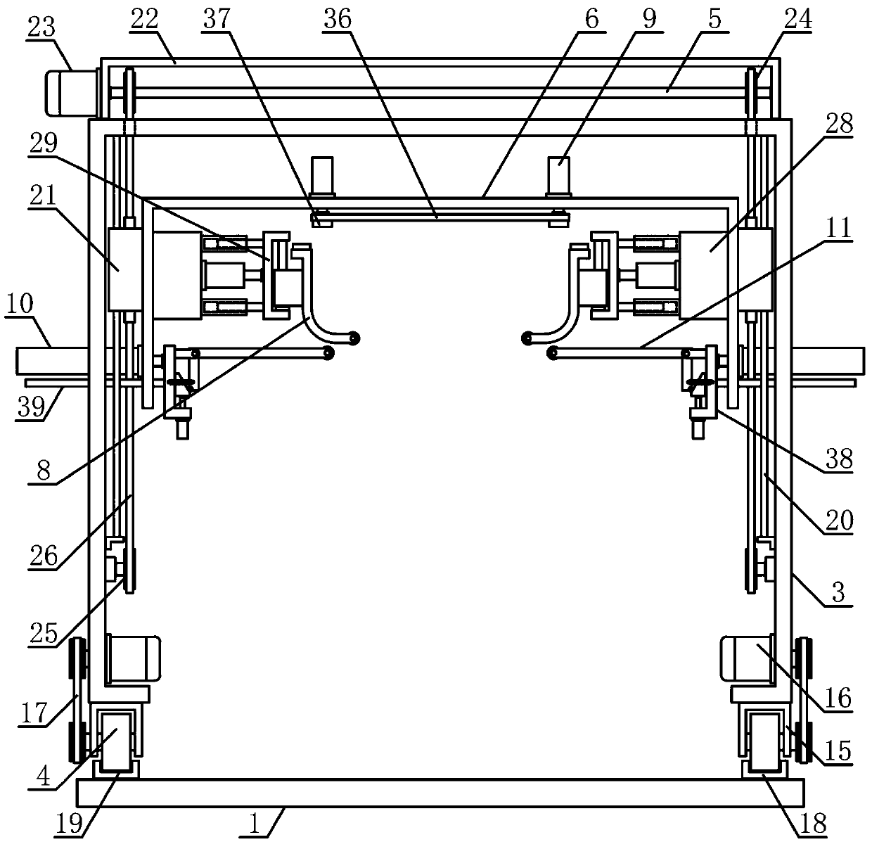
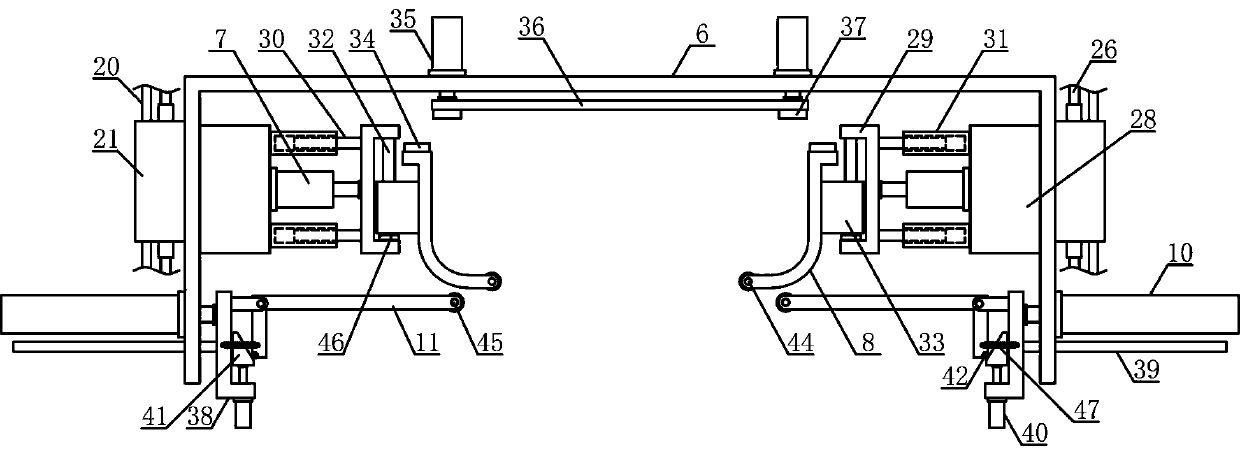
[0017] Such as figure 1 and figure 2 As shown, the transfer mechanism of a plastic particle storage bag of the present invention includes a feeding base 1, a material receiving base 2, a bag moving bracket 3, a translation guide wheel 4, a lifting shaft 5, a lifting bracket 6, an upper translation cylinder 7, a lift Bag pulling plate 8, bag carrying cylinder 9, lower translation cylinder 10, and bag holding plate 11, the material receiving base 2 is horizontally arranged on the upper side of the feeding base 1, and the upper side of the material receiving base 2 is horizontally provided with a bag receiving tray 12, Both sides ...


PUM


Abstract

The invention discloses a transferring mechanism of a plastic particle storage bag, and belongs to the field of plastic pipe production and machining mechanical equipment. The transferring mechanism is characterized in that a bag bearing tray is horizontally arranged on the upper side of a material bearing base, translation guide wheels are vertically arranged on the two sides of a guide wheel support below a bag moving support correspondingly, lifting guide plates on the two sides of the bag moving support are arranged on lifting guide rods in a sliding mode in the vertical direction, the twosides of a lifting support are fixedly connected with the lifting guide plates on the two sides of the bag moving support correspondingly, upper translation air cylinders are horizontally arranged onthe two sides of the interior of the lifting support correspondingly, bag lifting supports are arranged at the output ends of the upper translation air cylinders, bag lifting pull plates are horizontally arranged on one sides of bag lifting guide plates, lower translation air cylinders are horizontally and fixedly arranged in the middles of the two sides below the lifting support correspondingly,and bag placing bearing plates are arranged on the sides, at the output ends of the lower translation air cylinders, of reciprocating guide plates. The transferring mechanism is reasonable in structural design, woven bags containing plastic particles can be efficiently and stably conveyed and fed one by one, the automation degree is high, and the requirements of production and use are met.

Description

technical field [0001] The invention belongs to the field of plastic pipe production and processing machinery, in particular to a transfer mechanism for plastic particle storage bags, which is mainly used in the continuous production and processing of plastic pipes. Background technique [0002] As an important part of chemical building materials, plastic pipes are widely accepted by users for their superior performance, hygiene, environmental protection, and low consumption. They mainly include UPVC drainage pipes, UPVC water supply pipes, aluminum-plastic composite pipes, and polyethylene (PE) pipes. Water supply pipes, polypropylene PPR hot water pipes. Compared with cast iron pipes, galvanized steel pipes, cement pipes and other pipes, plastic pipes have the advantages of energy saving, environmental protection, light weight and high strength, corrosion resistance, smooth inner wall without scaling, easy construction and maintenance, and long service life. Pipes are wid...

Claims


Application Information

Patent Timeline
Patent Type & Authority Applications(China)
IPC IPC(8): B66F7/02B66F7/28
CPCB66F7/02B66F7/28
Inventor 胡建春
Owner 桐乡市建春塑业股份有限公司
Learn More