Grain drying device

A technology for grain drying and drying bins, which is applied in the direction of grain drying, drying, drying machines, etc., can solve the problems of poor drying effect and insufficient drying of grain, and achieves simple structure and easy popularization and application , Improve the effect of drying efficiency

Inactive Publication Date: 2020-05-15
杨文耀
View PDF5 Cites 6 Cited by
  • Summary
  • Abstract
  • Description
  • Claims
  • Application Information

AI Technical Summary

Problems solved by technology

[0004] The existing grain dryer accumulates grains in the drying chamber, so that the grains at the bottom cannot be fully dried, and the drying effect is not good

Method used


Image

  • Grain drying device
  • Grain drying device
  • Grain drying device

Examples


Embodiment 1

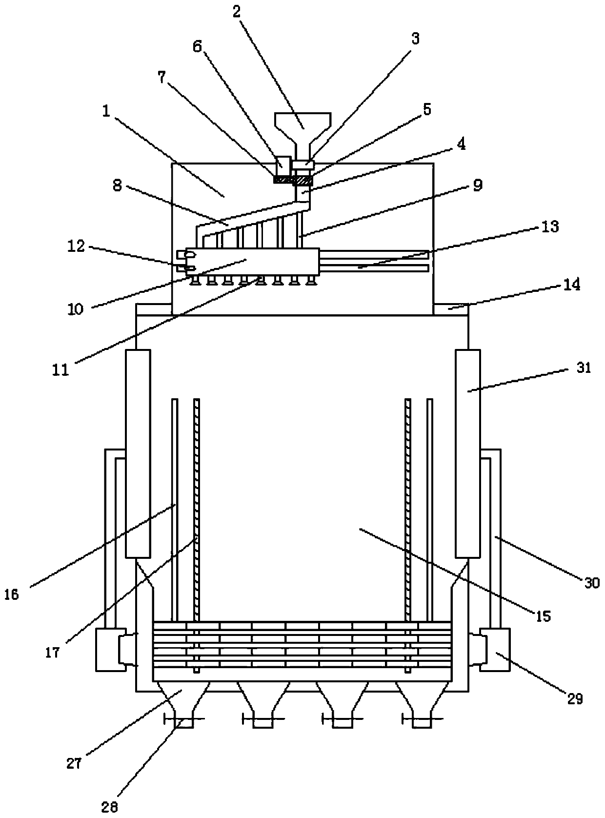
[0028] Embodiment 1: as Figure 1-7 As shown, a grain drying device includes a lower silo 1 and a drying silo 15, and the lower hopper 1 is located on the top of the drying silo 15;

[0029] A feed hopper 2 is fixedly installed at the top center of the lower hopper 1, and the grain is introduced into the lower hopper through the feed hopper;

[0030] The bottom end of the feed hopper 2 extends into the lower hopper 1, the bottom of the feed hopper 2 is fixedly equipped with a bearing 3, and the bottom of the feed hopper 2 is connected with a rotating tube 4 through the bearing 3. The bottom end of the rotating tube 4 is obliquely equipped with a drainage tube 8, and the drainage tube can rotate with the bearing;

[0031] The bottom of the drainage pipe 8 is fixedly equipped with some branch pipes 9, and the bottom of the branch pipe 9 is fixedly connected with a blanking bin 10, and the bottom of the blanking bin 10 is fixedly equipped with some feeding pipes 11, and the feed...

Embodiment 2

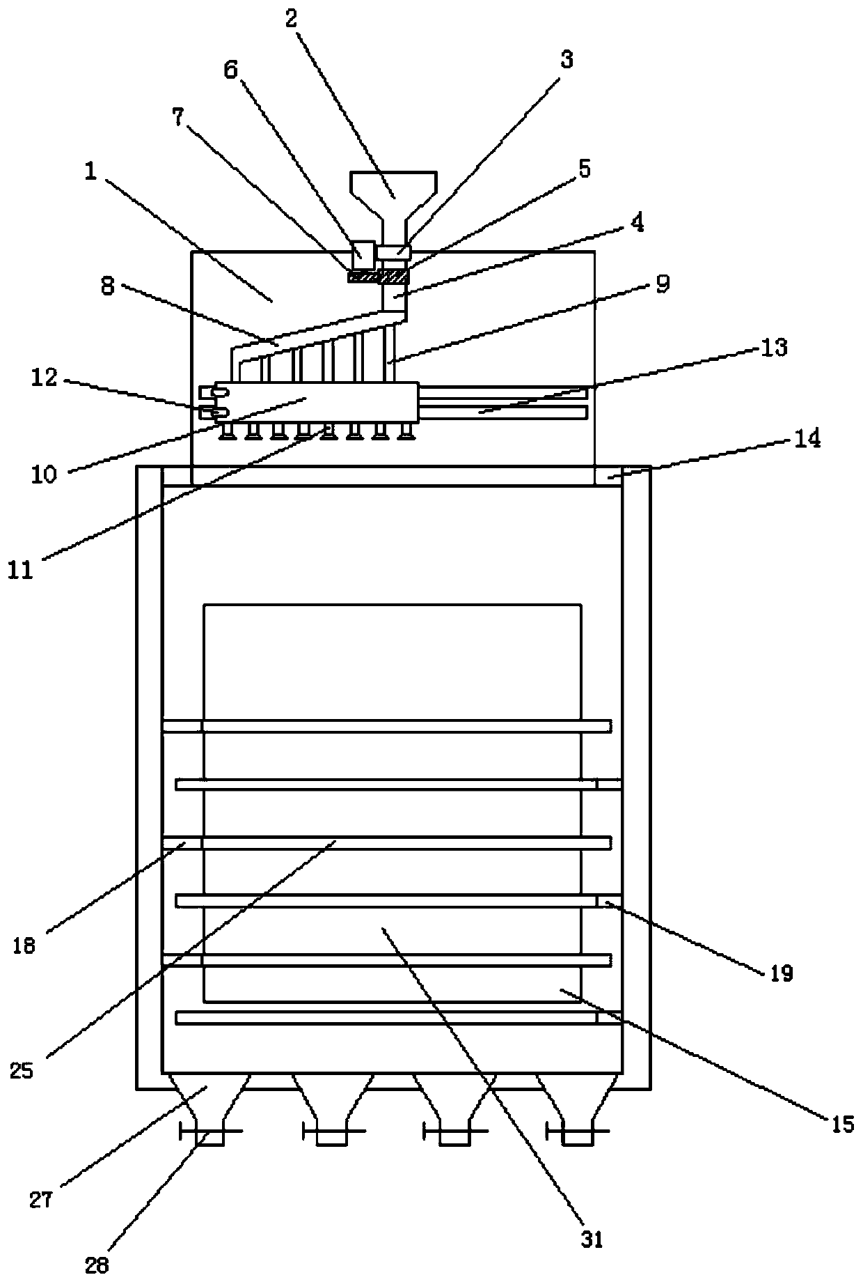
[0039] Embodiment 2: as Figure 1-8 As shown, a grain drying device includes a lower silo 1 and a drying silo 15, and the lower hopper 1 is located on the top of the drying silo 15;

[0040] A feed hopper 2 is fixedly installed at the top center of the lower hopper 1, and the grain is introduced into the lower hopper through the feed hopper;

[0041] The bottom end of the feed hopper 2 extends into the lower hopper 1, the bottom of the feed hopper 2 is fixedly equipped with a bearing 3, and the bottom of the feed hopper 2 is connected with a rotating tube 4 through the bearing 3. The bottom end of the rotating tube 4 is obliquely equipped with a drainage tube 8, and the drainage tube can rotate with the bearing;

[0042]The bottom of the drainage pipe 8 is fixedly equipped with some branch pipes 9, and the bottom of the branch pipe 9 is fixedly connected with a blanking bin 10, and the bottom of the blanking bin 10 is fixedly equipped with some feeding pipes 11, and the feedi...


PUM


Abstract

The invention discloses a grain drying device. The grain drying device comprises a feeding bin and a drying bin, and the feeding bin is located at the top of the drying bin; a feed hopper is fixedly mounted in the top center of the feeding bin; a first motor is fixedly mounted on the side wall of the feed hopper; two sets of rails and two sets of toothed rails are mounted on the side walls of thetwo sides of an inner cavity of the drying bin correspondingly, the rails on the side walls of the two sides of the inner cavity of the drying bin are movably connected with three sets of first lifting frames and second lifting frames correspondingly, two sets of second motors are fixedly mounted on the rear sides of the first lifting frame and the second lifting frame of each set, one sides of the second motors are fixedly connected with second gears, the second gears are mutually engaged with the corresponding toothed rails, and the inner side walls of the first lifting frames and the secondlifting frames are horizontally provided and connected with a plurality of sets of bearing plates; and a plurality of discharge hoppers are fixedly mounted at the bottom of the drying bin. The graindrying device is simple in structure, convenient and practical, grain can be distributed on all the bearing plates layer by layer, the drying area is increased, and the drying efficiency is improved.

Description

Technical field: [0001] The invention relates to the field of grain drying, in particular to a grain drying device. Background technique: [0002] Before storing grains such as rice and wheat, it is necessary to dry the grains. The usual method is to expose the grains to the sun. However, this drying method is inefficient and is easily affected by the weather and geographical environment. Many farmers expose the grains to the sun. There will also be safety hazards on the roadside, and now grain dryers are usually used instead of traditional grain drying methods. [0003] The grain dryer is mainly used for drying rice and wheat, and it can also be used for drying rapeseed and other crops after a little improvement. Grain dryer is composed of main components such as coal furnace, motor, axial flow fan and stacking rack. When the grain dryer is working, the motor drives the impeller of the axial flow fan to rotate at a high speed, so that the hot air generated by the combusti...

Claims


Application Information

Patent Timeline
Patent Type & Authority Applications(China)
IPC IPC(8): F26B9/06F26B21/00F26B25/00A23B9/08
CPCA23B9/08F26B9/066F26B21/001F26B21/004F26B25/002F26B2200/06
Inventor 杨文耀
Owner 杨文耀
Why Eureka
Try Eureka