Laser active tracking system and tracking method

An active tracking and laser technology, applied in the field of laser tracking, can solve the problems of data storage, real-time display and background upload, cannot guarantee the linearity of data acquisition, dynamic range, affect the accuracy and real-time performance of spot tracking, and achieve the acquisition time And the amount of data is reduced, the overhead of the circuit and memory is reduced, and the effect of facilitating data processing

Active Publication Date: 2020-05-15
AEROSPACE JINPENG TECH EQUIP (BEIJING) CO LTD
View PDF8 Cites 5 Cited by
  • Summary
  • Abstract
  • Description
  • Claims
  • Application Information

AI Technical Summary

Problems solved by technology

[0004] At present, the core technology in laser active tracking is how to measure the laser peak signal through four-quadrant photodetectors, "an optical precision tracking detector based on dual four-quadrant detectors (Chinese patent 200910093364.8)" and "a laser spot and return Wave tracking and monitoring device (Chinese patent 201811336974.1), all of which involve the above-mentioned applications, the common problem is that the captured signal is a solid-state laser pulse signal with a pulse width of 10-20ns and a repetition rate of 10-20Hz. There are mainly two methods of pulsed laser spot detection: peak hold and high-speed acquisition. The peak hold is to widen the nanosecond pulse signal incident on the detector to the microsecond level, and then use low-speed data acquisition for acquisition. The existing problem is that this This kind of broadening is based on the peak intensity of the pulse, which reduces the difficulty of data acquisition, but cannot guarantee the linearity and dynamic range of data acquisition, and cannot reflect the real parameters of the laser spot
In comparison, high-speed acquisition is an accurate solution, but for 10ns pulse signals, the ADC sampling rate of the sampling system needs to reach 1GS / s or more, coupled with a large amount of data from the image sensor, in tens of seconds to minutes Continuous work brings difficulties to data storage, real-time display and background upload, which ultimately affects the accuracy and real-time performance of spot tracking

Method used


Image

  • Laser active tracking system and tracking method
  • Laser active tracking system and tracking method
  • Laser active tracking system and tracking method

Examples


Embodiment Construction

[0035] The present invention will be described in further detail below in conjunction with the accompanying drawings and preferred examples.

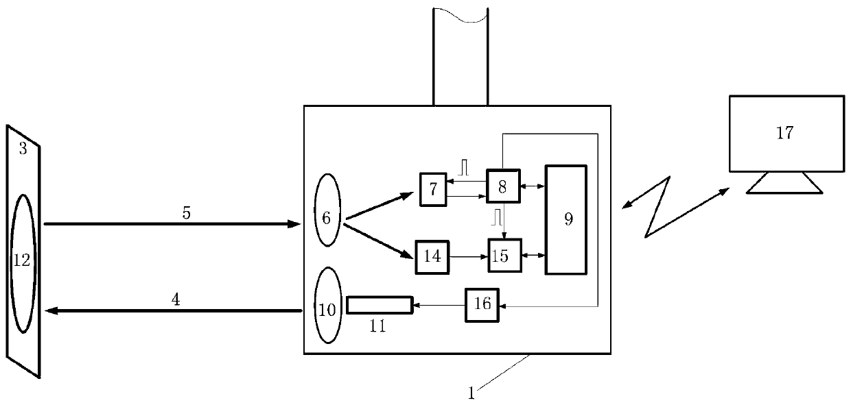
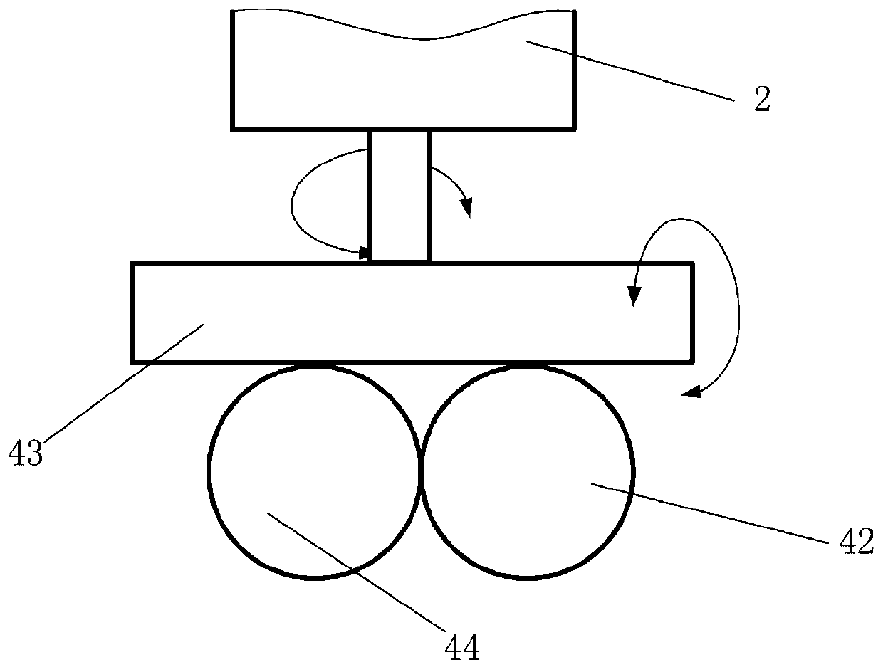
[0036] like figure 1 and figure 2 As shown, the laser active tracking system of the present invention includes a laser marker 42, a spot test unit 44 and a digital transmission unit 9; the laser marker 42 includes a transmitting mirror 10, a laser 11 and a laser driver 16; , four-quadrant photodetector 7, CCD imaging detector 14, CCD processing unit 15 and acquisition processing circuit 8;

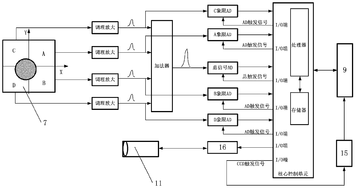
[0037] After the pulsed laser light emitted by the laser 11 irradiates the target 3 several kilometers away, its reflected light spot 12 is incident on the four-quadrant photodetector 7 and the CCD imaging detector 14 through the receiving mirror 6, and the CCD processing unit 15 controls the CCD imaging detector 14 processing to obtain the spot image; the acquisition and processing circuit 8 collects and processes the output electrical signal of...


PUM


Abstract

The invention discloses a laser active tracking system and tracking method. The system comprises a laser marker, a light spot test unit and a data transmission unit. The light spot test unit comprisesa receiving mirror, a four-quadrant photoelectric detector, a CCD imaging detector and an acquisition processing circuit; after pulse laser emitted by the laser irradiates a target, the CCD processing unit processes the CCD imaging detector to obtain a light spot image; the acquisition processing circuit acquires and processes an output electric signal of the four-quadrant photoelectric detectorto obtain a light spot centroid coordinate; the light spot image and the light spot centroid coordinate are sent to a far-end command and control center through the data transmission unit; according to the invention, the active tracking system integrates the four-quadrant detector, the CCD image sensor and the target indication laser together; the target indication laser emits pulse laser; comprehensive testing and target tracking of laser spots are achieved, and target parameters and decision basis reference are provided for accurate strike of semi-active guided weapons.

Description

technical field [0001] The invention belongs to the technical field of laser tracking, and mainly relates to an active tracking system and tracking method based on a four-quadrant detector, a CCD image sensor and a target indicating laser. Background technique [0002] The laser active tracking system consists of a four-quadrant laser spot tracking (LST), a laser spot tracking camera (CCD), and a laser target marker. Laser active tracking technology provides the tracking system with real-time information on the precise position of the target through the laser illumination mark of the target position. [0003] In the application of laser semi-active guided weapons, it is necessary to track the strike target. Usually, the laser active tracking system is installed on a helicopter or a fixed-wing aircraft to provide visual symbols for target indication and important target threat reminders for guided and unguided weapons. Combatants provide a guidance system for precision strik...

Claims


Application Information

Patent Timeline
Patent Type & Authority Applications(China)
IPC IPC(8): G01S17/66G01S17/89G01S7/4863
CPCG01S17/66G01S17/89G01S7/4863
Inventor 冯建新杜晋峰王冰
Owner AEROSPACE JINPENG TECH EQUIP (BEIJING) CO LTD
Why Eureka
Try Eureka